
Desulfurization device for petroleum smelting and operation method of device

A desulfurization device, petroleum smelting technology, applied in the direction of only multi-stage series refining process treatment, etc., can solve the problems of unsafe use, poor effect, complex structure, etc., and achieve the effect of strengthening desulfurization, improving desulfurization effect and desulfurization effect. Good results

Active Publication Date: 2019-08-23
HARBIN UNIV
View PDF3 Cites 0 Cited by
  • Summary
  • Abstract
  • Description
  • Claims
  • Application Information

AI Technical Summary

Problems solved by technology

[0004] The structure of the existing smelting desulfurization device is very complicated, the cost is also high, and it takes up a lot of space. Small enterprises with small sites cannot use such a smelting desulfurization device. The connection of the pipeline is not firm, it is not safe to use, and the effect is not good.

Method used


Image

  • Desulfurization device for petroleum smelting and operation method of device
  • Desulfurization device for petroleum smelting and operation method of device
  • Desulfurization device for petroleum smelting and operation method of device

Examples


Embodiment 1

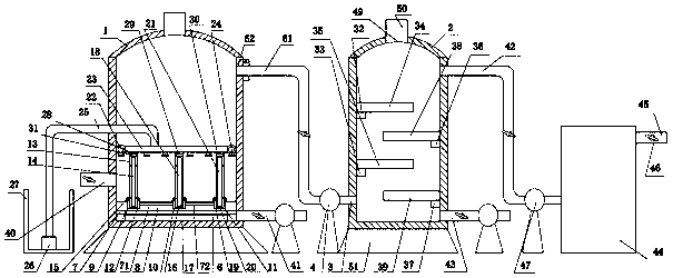
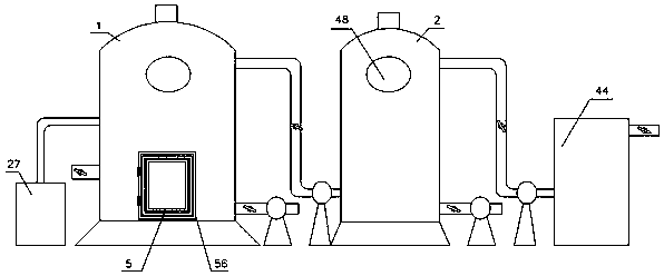
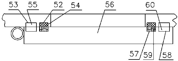
[0029] A petroleum smelting desulfurization device, which consists of: a No. 1 desulfurization tank 1 and a No. 2 desulfurization tank 2. The front side of the No. 1 desulfurization tank is provided with an inlet 5, and an ultrasonic generator is loaded along the inlet. 6, the No. 1 desulfurization tank has a side hole 62, the position of the side hole of the No. 1 desulfurization tank is welded with a U-shaped insert 63, and the bottom circle 7 is pasted inside the No. 1 desulfurization tank. The No. 1 desulfurization tank is welded to the bottom circle, the bottom circle is fixedly connected to the ring 8, the U-shaped insert is fixedly connected to the outer U-shaped stopper 64, and the No. 1 circulation oil pipe 61 is welded to a U-shaped Inserting plate 65, the U-shaped inserting plate is inserted into the inner side of the outer U-shaped retainer, and an outer sealing ring 66 is installed between the U-shaped insert and the outer U-shaped retainer. An inner sealing ring ...

Embodiment 2

[0031] In the petroleum smelting desulfurization device described in Example 1, the left half-mouth-shaped clamping member 12 is bonded to the left slot, and the primary filter device includes an elastic clamping frame 13, and the upper and lower sides of the primary filter membrane 14 All are connected with an elastic clamping frame 13, the cross-section of an elastic clamping frame is U-shaped, the elastic clamping frame clamps the primary filter membrane 14, and the left half mouth-shaped clamping member clamps Hold the bottom of the elastic clamping frame, the left and right sides of the left half mouth-shaped clamping piece 12 are connected with thumb screws 15, and the two thumb screws are relatively fastened to clamp the An elastic clip on the bottom of the frame.

[0032] An elastic clamping frame can hold the primary filter membrane very well, and it is connected and fixed by the left half-mouth-shaped clamping piece, and the left half-mouth-shaped clamping piece is r...

Embodiment 3

[0034] In the petroleum smelting desulfurization device described in Example 1, the middle slot is bonded with the half-mouth-shaped clamping member 16, and the secondary filter device includes two elastic clamping frames 17, and the upper and lower sides of the secondary filter membrane 18 Both are connected to two elastic clamping frames 17, the cross-section of the two elastic clamping frames is U-shaped, the two elastic clamping frames clamp the secondary filter membrane 18, and the middle half-mouth-shaped clamping member clamps Hold the bottom of the two elastic clamping frames, the left side and the right side of the middle half-mouth-shaped clamping piece 16 are connected with thumb screws, and the two thumb screws are relatively fastened to clamp the Two elastic clips are attached to the bottom of the frame.

[0035] The second elastic clamping frame can hold the secondary filter membrane very well, and it is connected and fixed through the half-mouth-shaped clamping ...


PUM


Abstract

The invention provides a desulfurization device for petroleum smelting and an operation method of the device. The device comprises a No.1 desulfurization tank and a No.2 desulfurization tank, the No.1desulfurization tank is provided with a side hole, the side hole position of the No.1 desulfurization tank is welded with a U-shaped insertion component, the U-shaped insertion component is fixedly connected with an outer U-shaped blocking component, a No.1 circulation oil tube is welded with a U-shaped insertion plate, the U-shaped insertion plate is inserted into the inner side of the outer U-shaped blocking component, an outer sealing ring is installed between the U-shaped insertion plate and the outer U-shaped blocking component, an inner sealing ring is installed between the U-shaped insertion plate and the No.1 desulfurization tank, the outer U-shaped blocking component is fastened with a half-opening shaped buckle cover, and a sealing gasket is pressed under the half-opening shapedbuckle cover; the No.1 circulation oil tube is connected with a circulation pump, the circulation pump is connected with a No.2 circulation oil tube, and the No.2 circulation oil tube is connected with the No.2 desulfurization tank; and the No.1 desulfurization tank is provided with an inlet, the No.1 desulfurization tank is attached with a bottom circle, the No.1 desulfurization tank is welded to the bottom circle, the bottom circle is fixedly connected with a circular ring, and the circular ring is provided with a left insertion groove, a middle insertion groove and a right insertion groove, the left insertion groove is filled with a primary filter device, the middle insertion groove is filled with a secondary filter device, and the right insertion groove is filled with a tertiary filter device. The desulfurization device provided by the invention is used for the petroleum smelting.

Description

[0001] Technical field: [0002] The invention relates to a petroleum smelting desulfurization device and an operation method. [0003] Background technique: [0004] The structure of the existing smelting desulfurization device is very complicated, the cost is high, and it takes up a lot of space. Small enterprises with small sites cannot use such a smelting desulfurization device. The connection of the pipeline is not firm, it is not safe to use, and the effect is not good. [0005] Invention content: [0006] The object of the present invention is to provide a petroleum smelting desulfurization device and an operation method that save space, are firmly connected, are more securely fixed, are stable in use, and have good use effects. [0007] Above-mentioned purpose realizes by following technical scheme: [0008] A petroleum smelting desulfurization device, which consists of: a No. 1 desulfurization tank and a No. 2 desulfurization tank. The front side of the No. 1 desulfu...

Claims


Application Information

Patent Timeline
IPC IPC(8): C10G53/02
CPCC10G53/02
Inventor 刘冉
Owner HARBIN UNIV
Learn More