
Interstage casing

An inter-stage, rectifying blade technology, applied in mechanical equipment, engine components, machines/engines, etc., can solve the problem of difficult to eliminate the flow separation of the inter-stage casing

Active Publication Date: 2019-08-23
AECC COMML AIRCRAFT ENGINE CO LTD
View PDF14 Cites 0 Cited by
  • Summary
  • Abstract
  • Description
  • Claims
  • Application Information

AI Technical Summary

Problems solved by technology

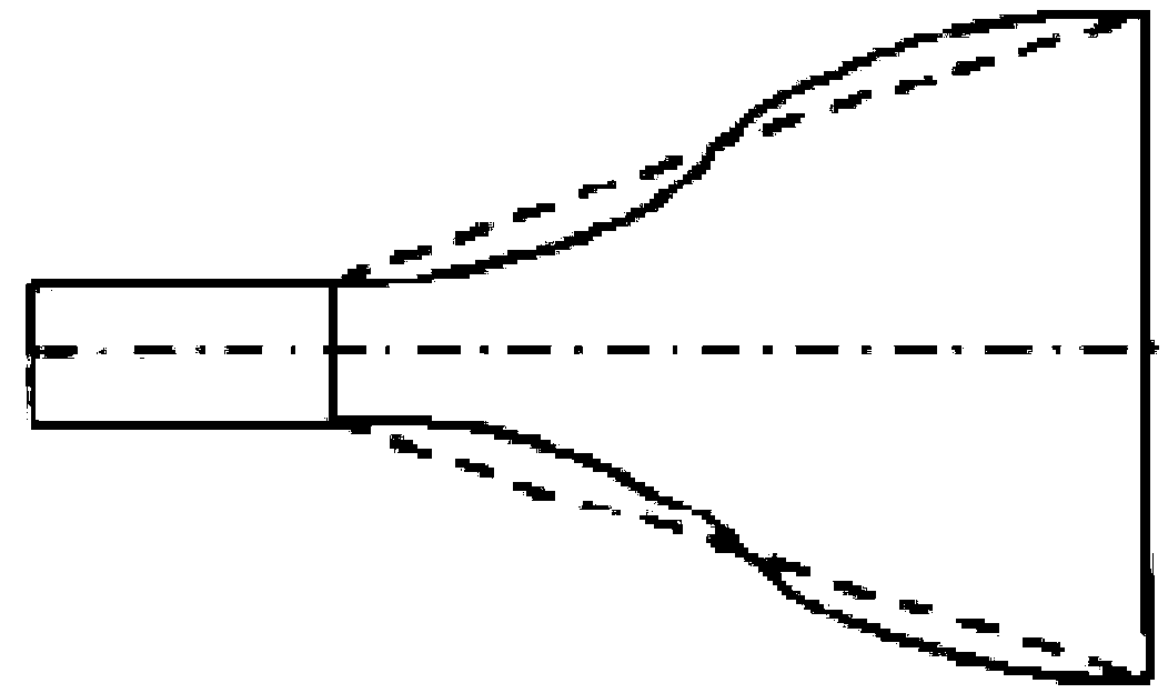
[0009] The technical problem to be solved by the present invention is to provide an interstage casing in order to overcome the defect that the flow separation in the interstage casing is difficult to eliminate in the prior art

Method used


Image

  • Interstage casing
  • Interstage casing
  • Interstage casing

Examples


Embodiment 1

[0045] Figure 7 It is a side view of Embodiment 1 of the interstage casing of the present invention. Figure 8 It is the rear view of Embodiment 1 of the interstage casing of the present invention. Figure 9 for Figure 8 Enlarged view of part A in Fig. Figure 10 It is a top view of Embodiment 1 of the interstage casing of the present invention. Figure 11 for Figure 10 Enlarged view of part B in .

[0046] Such as Figure 7 to Figure 11 As shown, the present invention discloses a turbine interstage casing, which includes an upper flow channel 20, a lower flow channel 30 and a rectifying vane 40, the rectifying vane 40 is connected between the upper flow channel 20 and the lower flow channel 30, and the rectifying vane 40 and the The junction of the upper channel 20 is provided with an axially front and back asymmetric rounded corner, the rounded corner includes a first chamfer 41 located at the front part of the rectifying vane 40 along the axial direction, and a first...

Embodiment 2

[0050] Figure 12 It is a partial enlarged view of the rear view of Embodiment 2 of the interstage casing of the present invention.

[0051] Such as Figure 12 As shown, the structure of this embodiment is basically the same as that of Embodiment 1, the difference is that the shape of the cold air holes 51 in this embodiment is square.

Embodiment 3

[0053] Figure 13 It is a partial enlarged view of the rear view of Embodiment 3 of the interstage casing of the present invention.

[0054] Such as Figure 13 As shown, the structure of this embodiment is basically the same as that of Embodiment 1, the difference is that the shape of the cold air holes 51 in this embodiment is triangular.


PUM


Abstract

The invention provides an interstage casing which comprises an upper runner, a lower runner and a straightening blade. The straightening blade is connected between the upper runner and the lower runner. Axial front and back non-symmetrical round-off angles are arranged at the connection part of the straightening blade and the upper runner. Each round-off angle comprises an axial first chamfer located on the front part of the straightening blade and an axial second chamfer located on the back part of the straightening blade. The first chamfer and the second chamfer are connected through an interface. A plurality of cold air holes are formed in the interface for improving a flow field. According to the turbine interstage casing, by trepanning and introducing cold air to blow down a low energy fluid with high losses in an angle area by means of the cold air between the straightening blade and a bearing supporting plate to increase the local flow rate and weaken the local axial and radialpressure gradient, and a purpose of improving the local flow field is achieved.

Description

technical field [0001] The invention relates to the field of gas turbine engines, in particular to an interstage casing. Background technique [0002] With the increase of the bypass ratio of civil aeroengines, whether it is the increase of the fan diameter or the decrease of the size of the core engine, the radial drop between the outlet of the high-pressure turbine and the inlet of the low-pressure turbine will increase. This will inevitably increase the pitch diameter expansion angle of the high and low pressure turbine interstage casing. At the same time, it is necessary to shorten the axial length of the interstage casing as much as possible to reduce its weight and thereby reduce the weight of the engine. Usually, the Mach number at the outlet of the high-pressure turbine is relatively high, which can reach 0.3-0.5. Under the same Mach number, the flow coefficient corresponding to the inlet stage of the low-pressure turbine is too high, which will lead to low efficie...

Claims


Application Information

Patent Timeline
IPC IPC(8): F01D9/00F01D25/24
CPCF01D9/00F01D25/24
Inventor 李蓓范宜龙侯伟涛
Owner AECC COMML AIRCRAFT ENGINE CO LTD
Learn More