Exhaust System For Use With A Turbine And Method Of Assembling Same

Active Publication Date: 2014-01-09
GENERAL ELECTRIC CO
View PDF4 Cites 0 Cited by
  • Summary
  • Abstract
  • Description
  • Claims
  • Application Information

AI Technical Summary

Benefits of technology

The patent describes a method of assembling an exhaust system for a steam turbine. The system includes an exhaust hood connected to the turbine, which has an aperture for fluid to enter. An ejector is also connected to the exhaust hood to reduce flow separation. The ejector has inlets and an outlet, and receives fluid from the exhaust hood through the aperture. The technical effect is a more efficient exhaust system that reduces fluid separation and improves overall performance.

Problems solved by technology

During low-load and / or start up conditions, steam leakage may occur near the inlet due to the high pressure of the incoming steam.
Moreover, during the same operating conditions, because a low pressure (LP) section of the turbine is under vacuum, an undesirable amount of atmospheric air may be drawn into the turbine system.
The abrupt change in the direction of the steam flow may cause the flow of steam to separate within the hood.
Flow separation may reduce static pressure recovery and reduce turbine efficiency.

Method used


Image

  • Exhaust System For Use With A Turbine And Method Of Assembling Same
  • Exhaust System For Use With A Turbine And Method Of Assembling Same
  • Exhaust System For Use With A Turbine And Method Of Assembling Same

Examples


Embodiment Construction

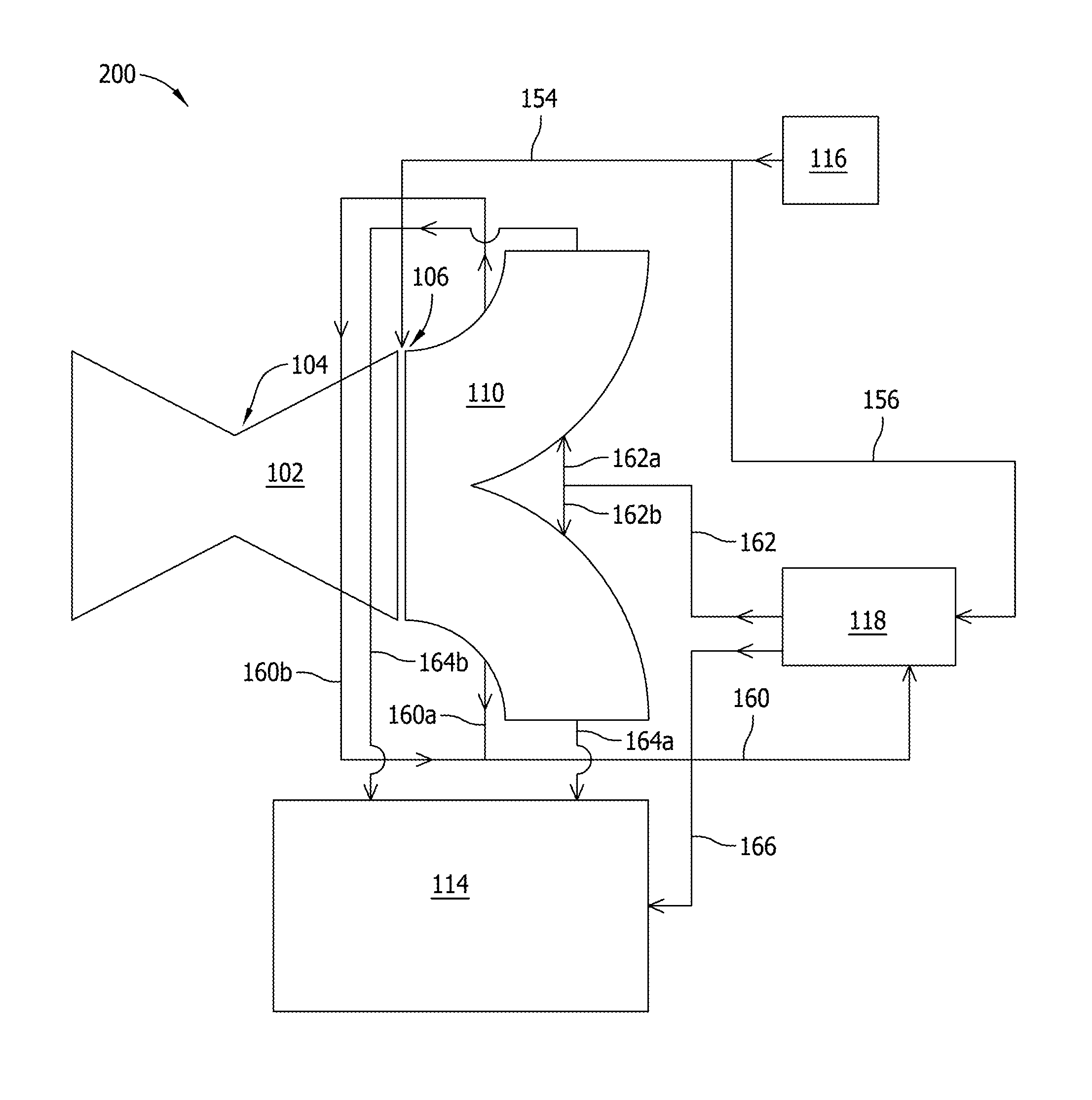
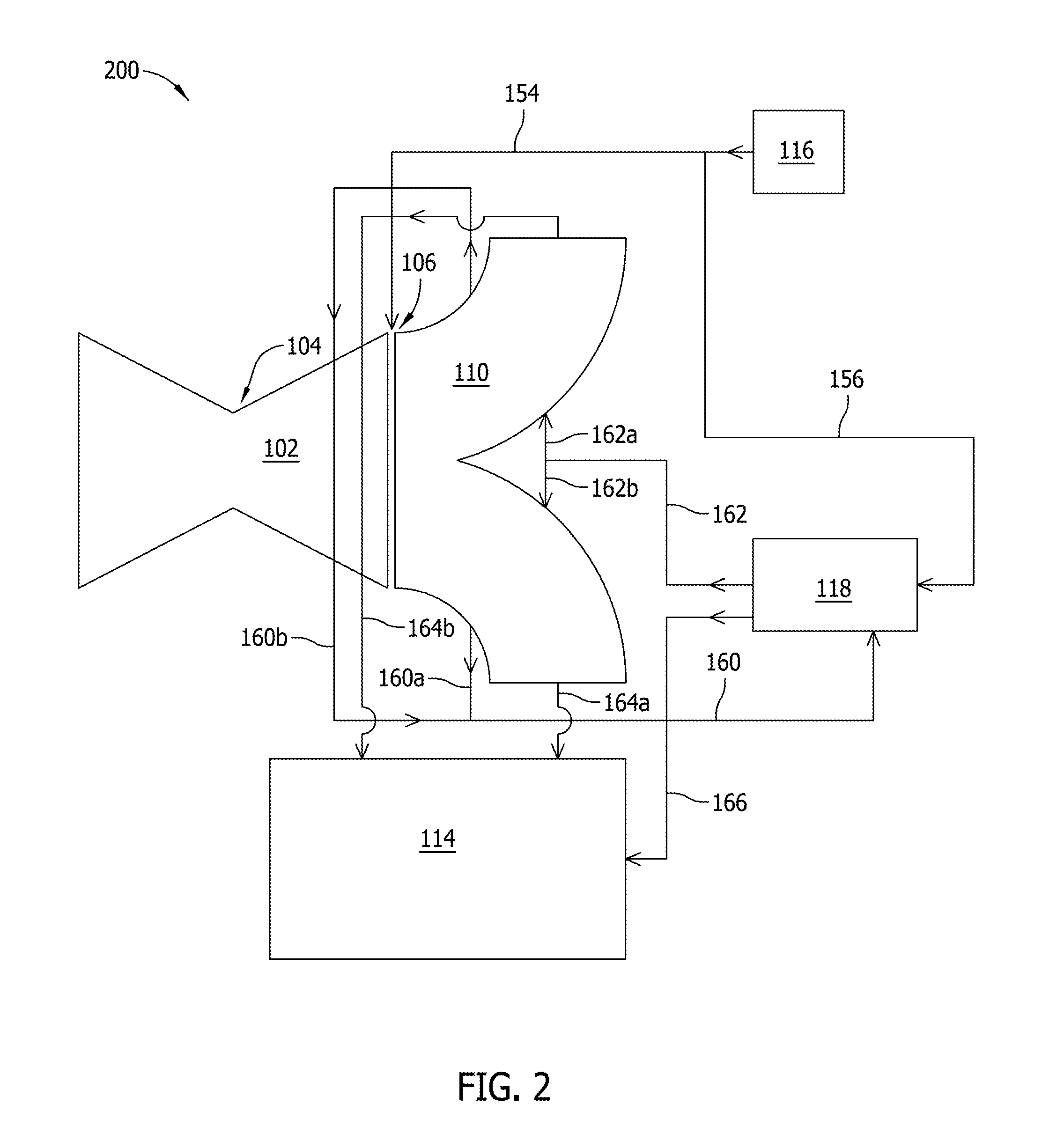
[0016]The methods and apparatus described herein are directed to an exhaust system that may be used with a turbine assembly. The exhaust system includes an exhaust hood and an ejector that work in combination to facilitate improved diffusion performance and improved static pressure recovery. More specifically, in the exemplary embodiment, the ejector is either a single-stage or a multi-stage ejector that facilitates reducing flow separation within the exhaust hood. Flow separation is reduced by inducing at least one of a suction effect and a blowing effect to the exhaust hood. As such, steam turbine efficiency is facilitated to be improved, and expenses associated with the turbine assembly are reduced.

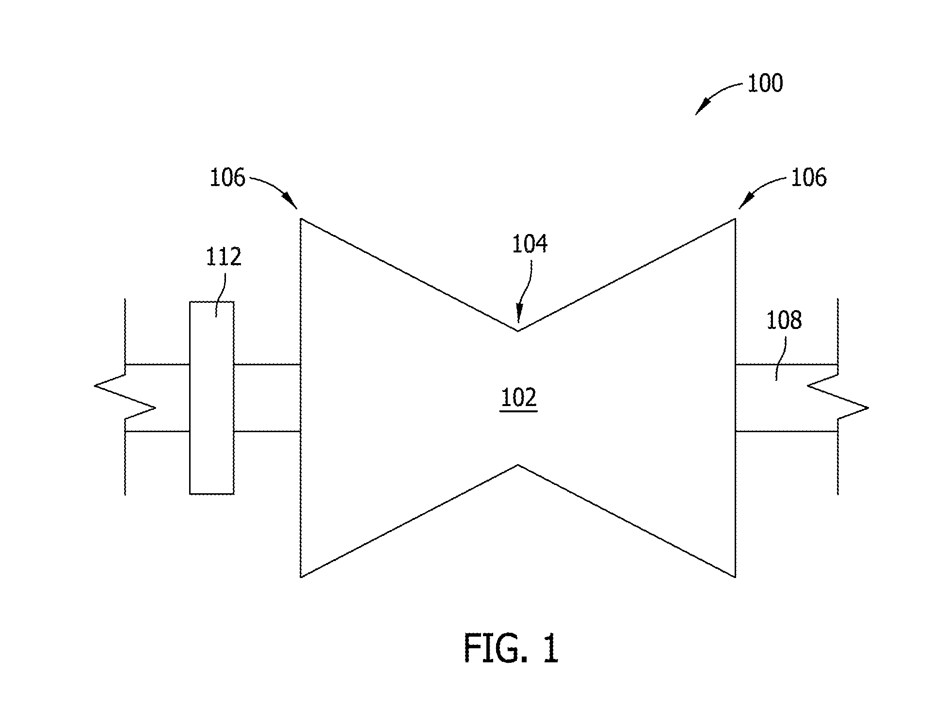
[0017]FIGS. 1 and 2 are schematic views of view of an exemplary steam turbine assembly 100 and an exemplary exhaust system 200. In the exemplary embodiment, turbine assembly 100 includes a steam turbine 102 that includes a high pressure (HP) section 104 and a low pressure (LP) section ...


PUM

PropertyMeasurementUnit
Pressureaaaaaaaaaa
Flow rateaaaaaaaaaa

Abstract

An exhaust system for use with a steam turbine is provided. An exhaust hood includes an input and an output, the input receiving fluid from the steam turbine. The exhaust hood includes a first side wall that extends between the input and the output. The first side wall includes an aperture. An ejector is coupled to the exhaust hood. The ejector includes inlets and an outlet. At least one of the inlets receives fluid from the exhaust hood via the aperture.

Description

STATEMENT REGARDING FEDERALLY SPONSORED RESEARCH & DEVELOPMENT[0001]This invention was made with Government support under Contract No. DE-FC26-05NT42643, awarded by the Department of Energy. The Government has certain rights in this invention.BACKGROUND OF THE INVENTION[0002]The subject matter disclosed herein relates generally to turbine engines and, more specifically, to exhaust systems for use with turbine engines.[0003]Rotary machines, such as steam turbines, may be used to generate power for electric generators. Known steam turbines have a steam path defined within a shell that includes, in serial-flow relationship, an inlet, at least one turbine, and an outlet. Known turbines include at least one row of circumferentially-spaced rotating buckets or blades.[0004]During low-load and / or start up conditions, steam leakage may occur near the inlet due to the high pressure of the incoming steam. Moreover, during the same operating conditions, because a low pressure (LP) section of th...

Claims


Application Information

Patent Timeline
IPC IPC(8): F04D23/00B23K3/00
CPCF01D25/30F01D25/305F05D2220/31F05D2260/601Y10T29/49234
Inventor DALSANIA, PRAKASH BAVANJIBHAISADHU, ANTANU
Owner GENERAL ELECTRIC CO
Why Eureka
Try Eureka