Exhaust centerbody for a turbine engine

a turbine engine and center body technology, applied in the direction of machines/engines, efficient propulsion technologies, manufacturing tools, etc., can solve the problems of reducing the efficiency generating significant separation of the flow of the gas stream, and risking the dynamics of the entire engine, so as to promote the flow separation and reduce vibration.

Active Publication Date: 2017-11-14
SN DETUDE & DE CONSTR DE MOTEURS DAVIATION S N E C M A
View PDF14 Cites 0 Cited by
  • Summary
  • Abstract
  • Description
  • Claims
  • Application Information

AI Technical Summary

Benefits of technology

[0010]The invention allows the upstream axial position of the flow separations to be precisely defined, this position corresponding to that of the ridge of the centerbody. Indeed, the ridge produces an annular region promoting the flow separations and limiting or even preventing the displacement of the front of the region of flow separation, thereby leading to a significant reduction in vibrations.
[0011]The truncated part of the body is designed to optimise the performance of the turbine engine, and in particular to maximise the pressure recovery on the body, which contributes to the thrust of the engine. The shape of this truncated part is defined in an axial section through half (axial half-section) of the outer surface of this part, that is to say by the outline or line produced by the outer surface of said part intersecting with a half-plane along the longitudinal axis of the body (and passing through an upper or lower half of the body). Each outline or line extends from the above-mentioned ridge towards the inside and downstream, as far as the axis A.

Problems solved by technology

However, within the context of calculations that are carried out to estimate the performance of a shortened body of this type, it has been noted that the shortened body generates significant separations of the flow of the gas stream.
The above-mentioned separations bring about a risk to the dynamics of the entire engine, since they may produce vibrations owing to the unsteady nature thereof (it being possible for the axial position of the separation front to vary over the outer surface of the body).

Method used


Image

  • Exhaust centerbody for a turbine engine
  • Exhaust centerbody for a turbine engine
  • Exhaust centerbody for a turbine engine

Examples


Embodiment Construction

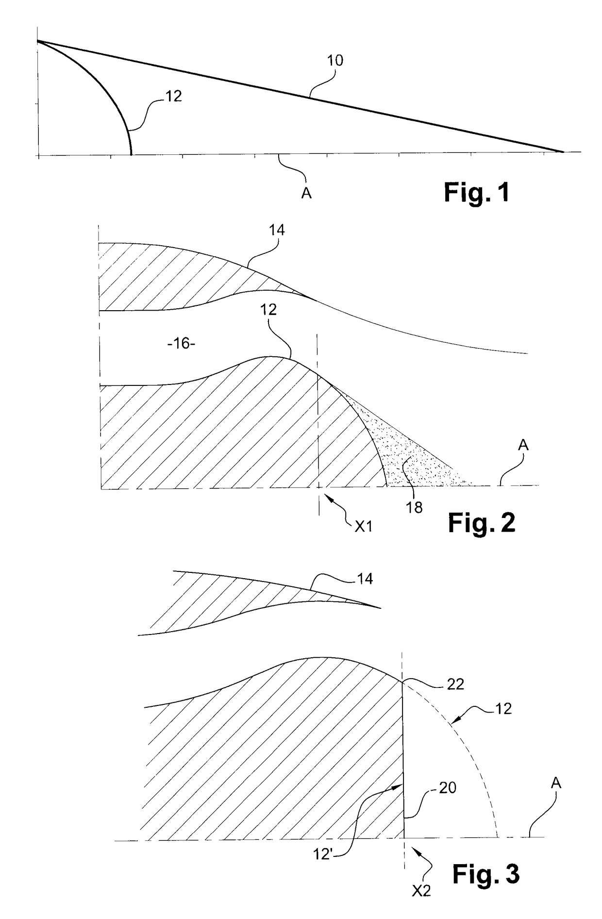
[0028]FIG. 1 highly schematically shows exhaust centerbodies 10, 12 for turbine engines, such as aircraft turbojets or turboprop engines, the body 10 having a conical shape and the body 12 having a rounded shape. These bodies 10, 12 have rotational symmetry about a longitudinal axis A, the tips thereof being oriented downstream and the upstream ends thereof each being intended to be generally fixed to an exhaust housing of the turbine engine. Downstream and upstream refer to the direction of flow of the air in the turbine engine.

[0029]As explained above, the body 12, which has a smaller axial length or dimension, has the advantage of having a lower mass. However, this body 12 promotes the separations of the flow of the gas stream exiting the turbine engine, as shown in FIG. 2.

[0030]This FIG. 2 shows a rounded centerbody 12 surrounded by an exhaust nozzle 14 of the turbine engine, and which centerbody defines, together with this nozzle, an annular exhaust channel 16 for the combustio...


PUM

PropertyMeasurementUnit
angleaaaaaaaaaa
angleaaaaaaaaaa
angleaaaaaaaaaa

Abstract

An exhaust centerbody for a turbine engine is provided. The centerbody includes a truncated downstream part, which is connected to an upstream part by an annular ridge marking a discontinuity between the outer surfaces of the upstream and downstream parts. The outer surface of the downstream part has a substantially conical general shape, of which the tip is oriented downstream and is positioned in the region of the axis A, the axial half-section of this outer surface defining a line of which the upstream end part is substantially tangential to a straight line passing through the ridge and forming a non-zero angle α with a tangent to the outer surface of the upstream part, in the region of the ridge, and of which the downstream end part is substantially tangential to a straight line passing through the tip and forming a non-zero angle β with the axis A.

Description

TECHNICAL FIELD[0001]The present invention relates to an exhaust centerbody for a turbine engine, such as an aircraft turbojet or turboprop engine.PRIOR ART[0002]An exhaust centerbody, also referred to as an exhaust cone (or plug), is positioned downstream of the turbine engine and is generally surrounded by the nozzle of the turbine engine, defining, together with said nozzle, an exhaust channel for the combustion gases from the engine.[0003]In general, a centerbody has a conical general shape of which the tip is oriented downstream and of which the upstream end is fixed to an exhaust housing of the turbine engine.[0004]It has already been proposed to axially shorten the exhaust centerbody of a turbine engine, in particular to reduce the mass thereof and to reduce the dynamic risks in the event of imbalance.[0005]However, within the context of calculations that are carried out to estimate the performance of a shortened body of this type, it has been noted that the shortened body ge...

Claims


Application Information

Patent Timeline
Patent Type & Authority Patents(United States)
IPC IPC(8): F02K1/04F02K1/82F01D25/30F01D5/14B64D33/04B23P23/00F01D17/14F01D25/04B21D53/84F01D17/10
CPCF02K1/04B21D53/84B23P23/00B64D33/04F01D5/143F01D17/10F01D17/145F01D25/04F01D25/30F02K1/82F01D17/141Y10T29/49323Y02T50/671Y02T50/673Y02T50/60
Inventor POUYAU, GUILLAUMESIRVIN, NICOLAS
Owner SN DETUDE & DE CONSTR DE MOTEURS DAVIATION S N E C M A
Why Eureka
Try Eureka