Diffuser suitable for vane pump

A technology of diffuser and vane pump, which is applied to parts, pumps, and pump elements of elastic fluid pumping devices, and can solve problems such as uneven pressure and velocity distribution, fluid energy loss, and unstable flow. Achieve the effect of reducing energy loss, obvious energy saving effect and improving flow field distribution

Inactive Publication Date: 2019-08-23
XIHUA UNIV +1
View PDF6 Cites 0 Cited by
  • Summary
  • Abstract
  • Description
  • Claims
  • Application Information

AI Technical Summary

Problems solved by technology

[0003] Due to the uneven pressure and velocity distribution of the fluid in the diffuser, it forms a complex three-dimensional flow in space, and various forms of vortices are formed in the diffuser flow channel, resulting in energy loss of the fluid and instability of the flow.

Method used


Image

  • Diffuser suitable for vane pump
  • Diffuser suitable for vane pump
  • Diffuser suitable for vane pump

Examples


Embodiment Construction

[0021] The present invention is further described below in conjunction with specific embodiment, and specific embodiment is the further description of the principle of the present invention, does not limit the present invention in any way, and the identical or similar technology of the present invention all does not exceed the scope of protection of the present invention.

[0022] In conjunction with the accompanying drawings.

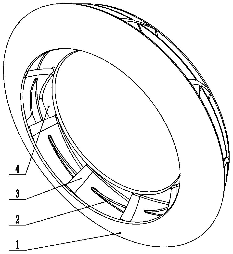
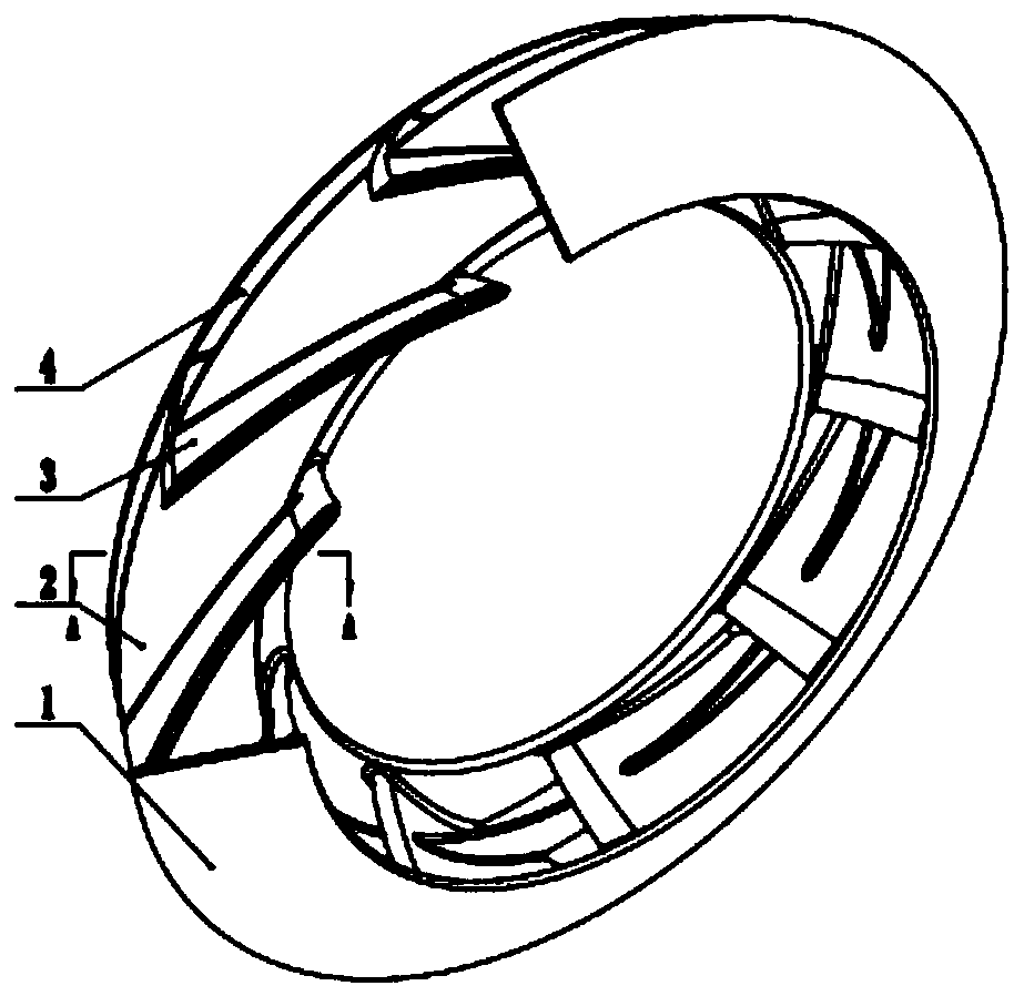
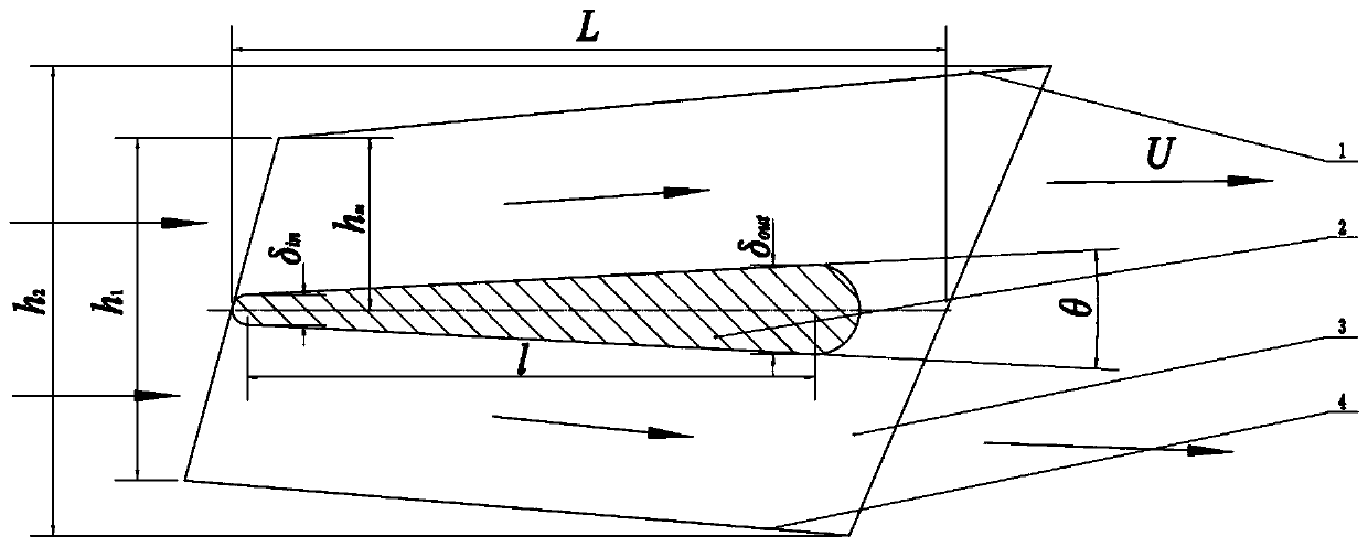
[0023] The present invention is suitable for the diffuser of vane pump to be made up of front cover plate 1 and rear cover plate 4 of planar annular structure, and the guide vane 3 that is arranged symmetrically between front cover plate 1 and rear cover plate 4, and front cover plate 1 Between the rear cover 4 and parallel to the planes of the front cover 1 and the rear cover 4 , there is an annular isolation plate 2 intersecting with each guide vane 3 .

[0024] The radial length l of the ring-shaped isolation plate 2 is smaller than the radial lengt...


PUM


Abstract

The invention discloses a diffuser suitable for a vane pump. The diffuser is composed of a front cover plate, a rear cover plate and guide vanes which are symmetrically arranged between the front cover plate and the rear cover plate; the front cover plate and the rear cover plate are each of a plane annular structure; isolation plates which are parallel to the planes of the front cover plate and the rear cover plate, crossed with the guide vanes and each of an annular structure are arranged between the front cover plate and the rear cover plate; and the radial length of the isolation plates ofthe annular structure is smaller than the radial length of the front cover plate or the rear cover plate. The inner diameter of the isolating plates is equal to the diameter of inlets of the guide vanes, and the outer diameter of the isolation plates is smaller than the diameter of outlets of the guide vanes. The diffuser structure can effectively improve the flow field distribution of the guidevanes or volutes of the diffuser of the vane pump, increase the flow stability, reduce the energy loss of fluid and improve the overall performance of the vane pump. After test measurement, it is found that the diffuser provided by the invention can improve the diffusion performance by 0.5%-2%, and the energy-saving effect is obvious.

Description

technical field [0001] The invention belongs to the technical field of design and manufacture of fluid transport pumps, and in particular relates to the design and manufacture of a diffuser suitable for vane pumps. Background technique [0002] In petrochemical, agricultural, and power industry applications, it is often necessary to use vane pumps to transport flowing media. The diffuser is an important component structure of the vane pump, including the guide vane or volute structure. As a key hydraulic component of the vane pump, the diffuser greatly affects the delivery efficiency. [0003] Due to the uneven pressure and velocity distribution of the fluid in the diffuser, it forms a complex three-dimensional flow in space, and various forms of vortices are formed in the diffuser flow channel, resulting in energy loss of the fluid and instability of the flow. With the development of technology and market demand, there is an urgent need for a diffuser that can improve the ...

Claims


Application Information

Patent Timeline
Patent Type & Authority Applications(China)
IPC IPC(8): F04D29/44F04D29/66
CPCF04D29/448F04D29/669
Inventor 文海罡刘清友叶道星张葛祥杨强王宇
Owner XIHUA UNIV
Why Eureka
Try Eureka