Horizontal underground culvert pipe blockage dredging robot and working method thereof

A horizontal and robotic technology, applied in the direction of special pipes, pipe components, mechanical equipment, etc., can solve problems such as complexity, large amount of engineering, and no cleaning equipment, so as to reduce workload, reduce dredging costs, and ensure dredging effect Effect

Active Publication Date: 2019-08-23
上海讯炅峰电路设计有限公司
View PDF13 Cites 7 Cited by
  • Summary
  • Abstract
  • Description
  • Claims
  • Application Information

AI Technical Summary

Problems solved by technology

[0004] As an important part of urban groundwater transportation, underground culvert pipes play an important role in the discharge of urban sewage or industrial wastewater produced by factory construction, but there will be certain blockages in both urban sewage and factory construction sewage supply roads However, the underground culverts are set under the surface, so we can only dig the ground, find the clogged point, dig the ground again, and replace the culverts at the clogged part. The amount of work is large and complicated; there is no special cleaning equipment

Method used


Image

  • Horizontal underground culvert pipe blockage dredging robot and working method thereof
  • Horizontal underground culvert pipe blockage dredging robot and working method thereof
  • Horizontal underground culvert pipe blockage dredging robot and working method thereof

Examples


Embodiment 1

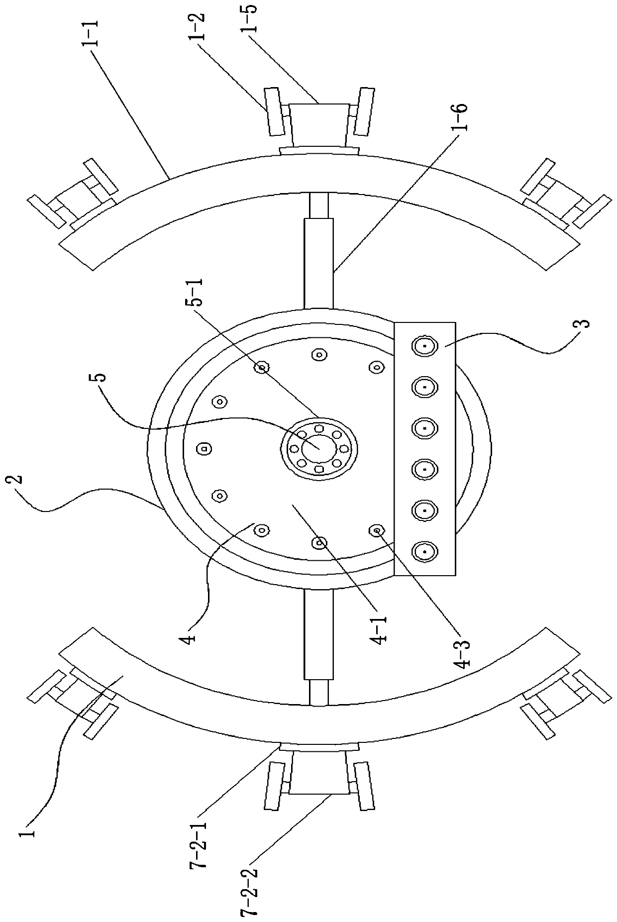
[0049] combine Figure 1-Figure 9 As shown, a horizontal underground culvert pipe blockage dredging robot disclosed in this embodiment includes a traveling mechanism 1, a dredging body 2, a beating dredging mechanism 3, a high-pressure dredging mechanism 4 and a camera mechanism 5; the dredging body 2 is arranged inside the walking mechanism 1, and the front end of the dredging body 2 is provided with a high-pressure dredging mechanism 4, and the high-pressure dredging mechanism 4 is connected to an external high-pressure water pump through a transmission line 6, and the high-pressure water pump is connected to an external water source The camera mechanism 5 is arranged in the middle of the high-pressure dredging mechanism 4, and the camera mechanism 5 is connected to the external host computer through the transmission line 6. A silting mechanism 3, the rear end of the dredging fuselage 2 is provided with a driven walking mechanism 7;

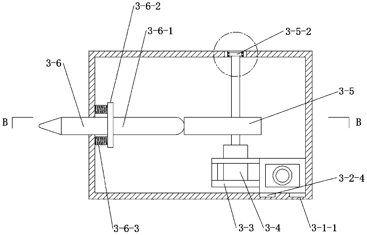
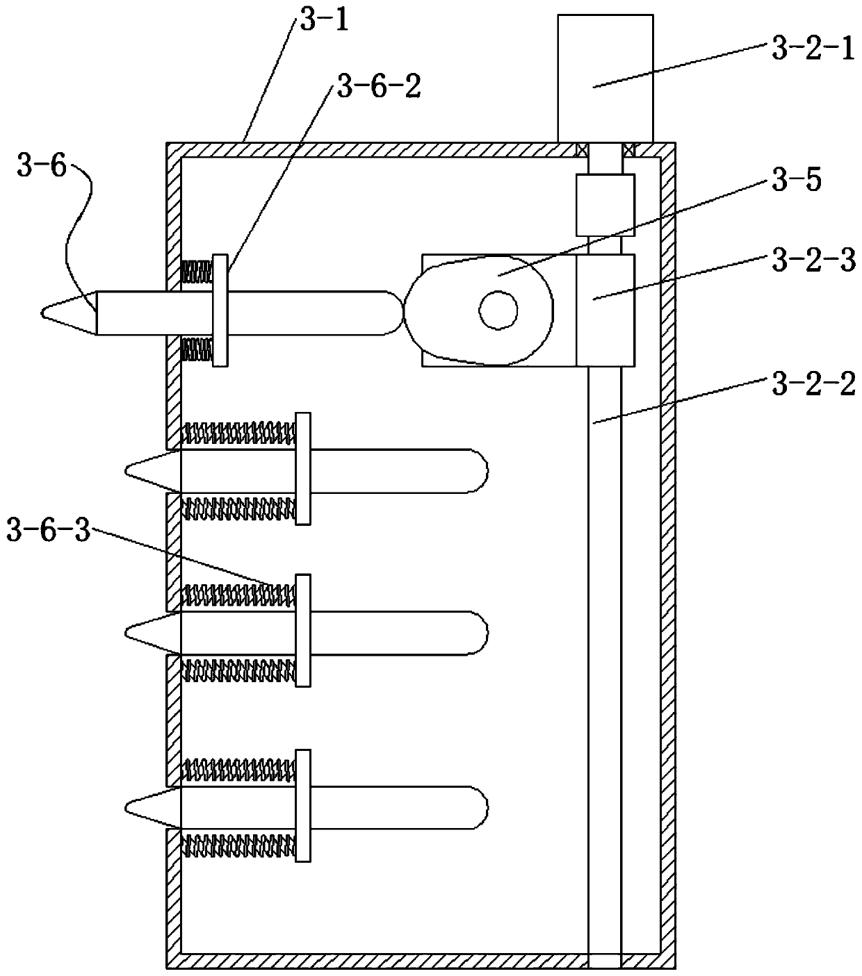
[0050] The beating and dredging mechani...

Embodiment 2

[0053] On the basis of Embodiment 1, the walking mechanism 1 in this embodiment includes two sets of symmetrically arranged arc-shaped walking plates 1-1, and the outer end faces of the arc-shaped walking plates 1-1 are equidistantly provided with three sets of driving and moving rollers. 1-2, each of the driving mobile rollers 1-2 is fixedly connected to the main shaft of a group of roller driving motors 1-3, and the roller driving motors 1-3 are arranged on the driving roller frame 1 through the shock absorbing device 1-4 -5, the driving roller frame 1-5 is arranged on the outer end surface of the arc-shaped walking plate 1-1, and the arc-shaped walking plate 1-1 connects with the dredging body through the culvert tube adaptive device 1-6 2 fixed connections;

[0054] The driven traveling mechanism 7 includes two groups of symmetrically arranged driven arc-shaped plates 7-1, and three sets of driven rollers 7-2 are equidistantly arranged on the outer end surface of the drive...

Embodiment 3

[0056] On the basis of Embodiment 1, the shock absorber 1-4 in this embodiment includes a group of lower shock absorbers 1-4-2 and upper shock absorbers 1-4-1, and the driving roller frame 1-5 and The driven roller 7-2 frames all include a set of installation arc plates 7-2-1, and the installation arc plates 7-2-1 are welded on the arc walking plate 1-1 and the driven rollers. On the arc-shaped plate 7-1, a group of installation columns 7-2-2 are welded on the installation arc-shaped plate 7-2-1, and shock-absorbing grooves are processed on the installation columns 7-2-2. The bottom end of the shock absorbing groove is fixed with the lower shock absorbing device 1-4-2, and the lower shock absorbing device 1-4-2 is connected with the roller drive motor 1-3 and the driven roller 7-2. The rotating shaft bearings are fixedly connected, and the upper ends of the rotating shaft bearings of the roller drive motor 1-3 and the driven roller 7-2 are also connected with the upper shock a...


PUM


Abstract

The invention provides a horizontal underground culvert pipe blockage dredging robot and a working method thereof. The robot comprises a travelling mechanism, a dredging machine body, a beating and dredging mechanism, a high-pressure dredging mechanism and a camera shooting mechanism, wherein the dredging machine body is arranged in the travelling mechanism, the high-pressure dredging mechanism isarranged at the front end of the dredging machine body, the high-pressure dredging mechanism is connected with an external high-pressure water pump through a conveying line, the high-pressure water pump is connected with an external water source, the camera shooting mechanism is arranged in the middle of the high-pressure dredging mechanism, the camera shooting mechanism is in data connection with an external upper computer through the conveying line, the beating and dredging mechanism are further arranged at the lower end of the high-pressure dredging mechanism, and a driven travelling mechanism is arranged at the rear end of the dredging machine body. According to the robot and the method, the travelling mechanism is arranged, so that a robot can travel in a culvert pipe, the influencein the culvert pipe is collected through the camera shooting mechanism and is transmitted back to the upper computer until a blocking point is found, the blockage is dredged by the cooperation of thebeating and dredging mechanism and the high-pressure dredging mechanism, so that the dredging of the culvert pipe blockage is completed.

Description

[0001] Technical field: [0002] The invention relates to the technical field of an underground culvert pipe dredging robot, in particular to a horizontal underground culvert pipe blockage dredging robot and a working method thereof. [0003] Background technique: [0004] As an important part of urban groundwater transportation, underground culvert pipes play an important role in the discharge of urban sewage or industrial wastewater produced by factory construction, but there will be certain blockages in both urban sewage and factory construction sewage supply roads However, the underground culverts are set under the surface, so we can only dig the ground, find the clogged point, dig the ground again, and replace the culverts at the clogged part. The amount of work is large and complicated; there is no special cleaning equipment. [0005] Invention content: [0006] The present invention overcomes the deficiencies of the prior art above, and provides a robot for unblocking h...

Claims


Application Information

Patent Timeline
Patent Type & Authority Applications(China)
IPC IPC(8): F16L55/32F16L101/10
CPCF16L55/32F16L2101/10
Inventor 任振强
Owner 上海讯炅峰电路设计有限公司
Why Eureka
Try Eureka