Dredging equipment for water conservancy river channel

A technology for river channels and equipment, applied in mechanically driven excavators/dredgers, construction, earthmoving machines/shovels, etc. Reduce the cost of dredging, improve treatment efficiency, and improve the effect of dredging

Pending Publication Date: 2022-04-22
亓会中
View PDF7 Cites 1 Cited by
  • Summary
  • Abstract
  • Description
  • Claims
  • Application Information

AI Technical Summary

Problems solved by technology

[0004] Some small man-made rivers are actually still stagnant water. As time goes by, there will often be silt deposits in the river, and some debris will remain on the bottom of the river. These silt and debris will not be cleaned up easily for a long time. Smell, not only affect the water quality but also pollute the environment;
[0005] When cleaning it, in related technologies, it is usually necessary to close the river channel, drain the river water in the closed section of the channel, and then use a high-pressure water gun to wash the river bottom to form muddy water, and finally use a sludge pump to pump the muddy water from the river bottom The whole cleaning process is more troublesome and costly;
[0006] In addition, when the existing river channel dredging device is in use, the cleaning effect on the difficult-to-handle deposits in the channel is average. The silt deposited on the bottom of the river will be blown and stirred into turbid water by mechanical equipment, and it will flow away with the river. Thereby playing the role of dredging, but it is easy to form silt again after a period of time, and there is more sewage in the cleaned river, and the harmful substances in the silt are also easy to spread to various positions in the river, affecting water quality and appearance. On the one hand, the sludge after dredging is difficult to handle, which affects the overall dredging efficiency. Based on this, the present invention designs a dredging equipment for water conservancy channels to solve the above problems

Method used


Image

  • Dredging equipment for water conservancy river channel
  • Dredging equipment for water conservancy river channel
  • Dredging equipment for water conservancy river channel

Examples


Embodiment 1

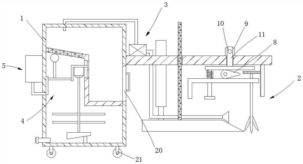
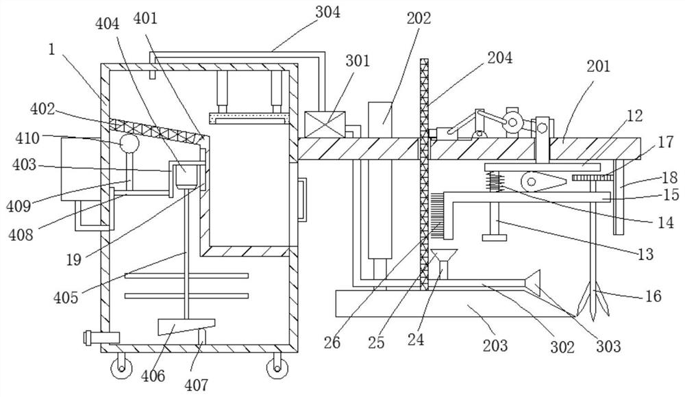
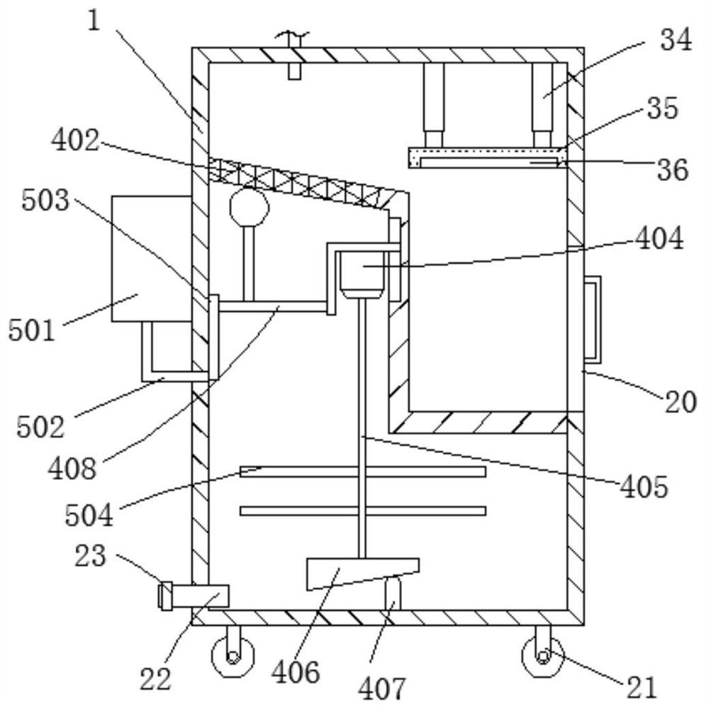
[0038] see Figure 1-6 , the present invention provides a technical solution: a dredging equipment for water conservancy rivers, including a main body box 1, a loosening mechanism 2, a suction mechanism 3, a separation mechanism 4 and a processing mechanism 5, and the loosening mechanism 2 includes a horizontal plate 201, telescopic rod 202, push plate 203 and filter screen 204, horizontal plate 201 is horizontally fixed on the right side of main body box 1, telescopic rod 202 is plugged on the horizontal plate 201, and push plate 203 is fixedly connected to the output of telescopic rod 202 end, and the right end of the push plate 203 is inclined, the filter screen 204 is vertically fixed on the top of the push plate 203, the horizontal plate 201 is provided with a through groove 6, and the filter screen 204 extends to the top of the horizontal plate 201 through the through groove 6 .

[0039] Wherein, the loosening mechanism 2 also includes a motor 9, a screw mandrel 10, a m...

Embodiment 2

[0045] Compared with embodiment 1, its difference is:

[0046] Wherein, the bottom of horizontal plate 201 is also provided with cleaning mechanism, and cleaning mechanism comprises branch pipe 24, the second mud suction cover 25 and cleaning brush 26, and branch pipe 24 is vertically arranged on the position of connecting pipe 302 near the right side of filter screen 204, and the second The mud pumping cover 25 is installed on the end of the branch pipe 24, the lifting rod 15 is L-shaped, and the cleaning brush 26 is bonded to the side of the lifting rod 15 near the filter screen 204.

Embodiment 3

[0048] Compared with embodiment 2, its difference is:

[0049] Wherein, the top of horizontal plate 201 is also provided with auxiliary mechanism, and auxiliary mechanism comprises support rod 27, rotating disk 28, connecting rod 29, slide block 30 and projection 31, and supporting rod 27 is affixed on the top of horizontal plate 201, and rotating disk 28 rotates Connected to the front side of the support rod 27, a transmission member 32 is provided between the turntable 28 and the screw mandrel 10, and a slide rail 33 is provided on the top of the horizontal plate 201, the slide block 30 is slidably connected to the slide rail 33, and the connecting rod 29 is hinged On the horizontal plate 201 , the left and right ends of the connecting rod 29 are respectively hinged with the turntable 28 and the slider 30 , and the projection 31 is fixedly connected to the side of the slider 30 close to the filter screen 204 .


PUM


Abstract

The invention provides desilting equipment for a water conservancy riverway, and relates to the technical field of water conservancy riverway desilting, the desilting equipment comprises a main body box, a stirring loosening mechanism, a suction mechanism, a separation mechanism and a treatment mechanism, the stirring loosening mechanism comprises a transverse plate, a telescopic rod, a push plate and a filter screen, the transverse plate is horizontally and fixedly connected to the right side of the main body box, and the telescopic rod is inserted into the transverse plate; the push plate is fixedly connected to the output end of the telescopic rod, the right end of the push plate is obliquely arranged, the filter screen is vertically and fixedly connected to the top of the push plate, a through groove is formed in the transverse plate, and the filter screen extends to the position above the transverse plate through the through groove. And in addition, when the movable rod moves, the filter screen can be cleaned through the cleaning brush, blockage of the filter screen is avoided, the effect is better when the filter screen blocks turbid water during treatment, and the overall dredging effect is improved.

Description

technical field [0001] The invention relates to the technical field of dredging water conservancy rivers, in particular to a dredging equipment for water conservancy rivers. Background technique [0002] Water conservancy engineering is a project built to control and allocate natural surface water and groundwater to achieve the purpose of eliminating harm and rejuvenating benefits, also known as water engineering; water is an indispensable precious resource for human production and life, but its natural existence The state does not fully meet the needs of human beings. Only by building water conservancy projects can water flow be controlled, floods prevented, and water volume adjusted and distributed to meet the needs of people's life and production for water resources; water conservancy projects require the construction of dams, dikes, Spillways, sluices, water inlets, canals, waterways, rafts, fishways and other different types of hydraulic structures to achieve their goal...

Claims


Application Information

Patent Timeline
Patent Type & Authority Applications(China)
IPC IPC(8): E02F5/28E02F5/30E02F3/88E02F3/90
CPCE02F5/28E02F5/30E02F3/88E02F3/90
Inventor 亓会中王树
Owner 亓会中
Why Eureka
Try Eureka