Equipment realizing quick measurement on small assembling clearance

An assembly gap and fast technology, applied in measuring devices, optical devices, instruments, etc., can solve problems such as high requirements for professional knowledge, difficult on-site application by workers, and low degree of automation

Active Publication Date: 2019-08-23
CHINESE AERONAUTICAL RADIO ELECTRONICS RES INST
View PDF7 Cites 6 Cited by
  • Summary
  • Abstract
  • Description
  • Claims
  • Application Information

AI Technical Summary

Problems solved by technology

Although the digital display vernier caliper can effectively improve the efficiency of inspectors, this method still has the following problems: (1) the measurement process is complicated, and each size must be compared repeatedly; (2) the degree of automation is low, when the size calculation is required , the inspectors have to calculate manually, which is prone to errors; (3) The proficiency and technique of the inspectors may affect the measurement results; (4) The contact measurement method is a destructive measurement method, which may cause scratches, bumps and other damage to the product , especially during electrical component measurements
In short, the traditional measurement method has many problems such as poor accuracy, low efficiency, error-prone, and possible damage to devices, which brings great troubles to production
[0009] At present, in the electronic product production industry with large batches, an advanced non-contact measurement method is widely used, using lasers, cameras and other acquisition equipment to collect product surface features, and perform automatic comparison calculations, which can eliminate human interference and realize complex structures. At the same time, the acquisition speed is extremely fast, and damage to components can also be avoided. However, the measurement method and measurement principle of this measurement equipment require high professional knowledge, such as image processing, coordinate transformation, feature fitting, etc., and the software operation is complicated. , It is difficult for workers to apply it on site, and it is difficult to apply to the production process of small batches and various types of products

Method used


Image

  • Equipment realizing quick measurement on small assembling clearance
  • Equipment realizing quick measurement on small assembling clearance
  • Equipment realizing quick measurement on small assembling clearance

Examples


Embodiment Construction

[0035] The present invention will be further described in detail below in conjunction with the accompanying drawings and embodiments.

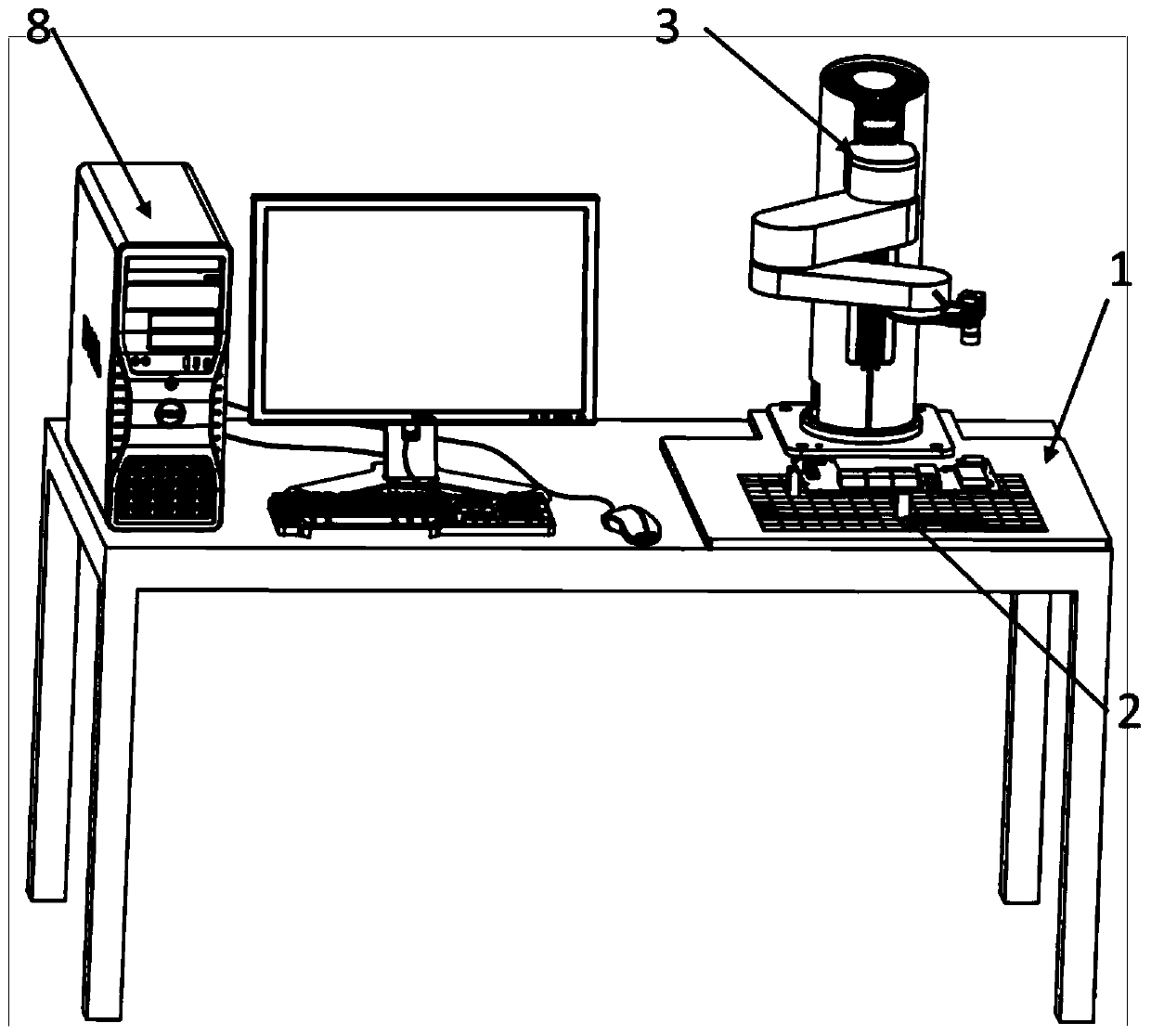
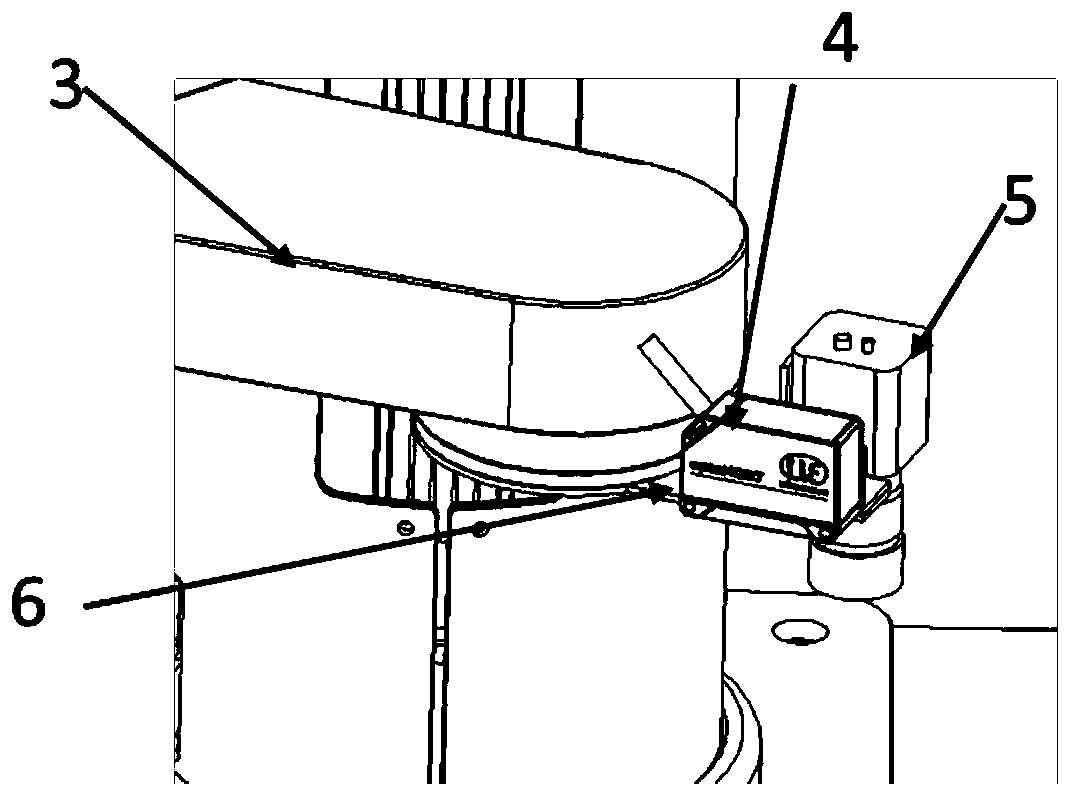
[0036] A kind of equipment that realizes the rapid measurement of tiny assembly gap shown in this embodiment, see figure 1 As shown, it mainly includes: a base 1, a support 2, a horizontal four-axis collaborative robot 3 and an industrial computer 8.

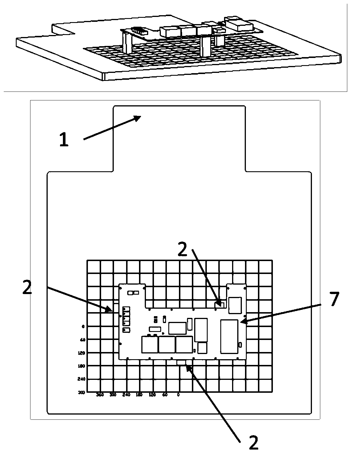
[0037] The base 1 is used to install the horizontal four-axis collaborative robot 3 and the parts 7 to be tested. Its features include: adopting stainless steel plate and weight-reducing design, the surface is polished and smooth, setting mutually perpendicular rectangular grooves to form grid lines, and marking the scale value according to the groove position.

[0038] Bearing 2 has 3-6, is placed on the base. The bottom of the support is designed with a magnetic device, which can be adsorbed on the base and can be manually moved to different positions as needed. There is a 2mm step on the ...


PUM


Abstract

The invention discloses equipment realizing quick measurement on a small assembling clearance. The equipment contains a base, a plurality of supports, a horizontal four-axis collaborative robot and anindustrial control computer, wherein the base is provided with grid lines and scale values, the supports are used for fixing and supporting a to-be-measured part and locating and placing the to-be-measured part according to the scale values, an industrial camera and a laser displacement sensor are mounted at the tail end of the horizontal four-axis collaborative robot by virtue of a connecting plate, and the industrial control computer executes the following operations: controlling the horizontal four-axis collaborative robot to move the industrial camera to a position above the to-be-measured part and controlling the industrial camera to obtain an image of the to-be-measured part, generating an interface used for confirming locating points on the image by a user and recording the locating points, controlling the horizontal four-axis collaborative robot to move the laser displacement sensor to the locating points and controlling the laser displacement sensor to measure data, and calculating height of the clearance according to the measured data. The equipment disclosed by the invention is high in precision and simple to operate, an operator can easily use after simple learning, and a production requirement of multi-variety and small-batch products can be met.

Description

technical field [0001] The invention relates to the field of product assembly production and manufacturing, in particular to a device for automatic measurement of tiny gaps during the sticking process of electronic product chip heat conduction pads. Background technique [0002] As electronic devices continue to pack more powerful features into smaller components, rising temperatures can cause devices to slow down, devices to fail mid-operation, size and space constraints, and many other performance issues. In order to effectively control the temperature of the device, a thermally conductive filling material is widely used in electronic and electrical products, namely thermally conductive silicone pads, referred to as thermally conductive pads. The thermal pad has a certain degree of flexibility, excellent insulation, compressibility and natural stickiness on the surface. It completes the heat transfer between the heating part and the heat dissipation part by filling the abb...

Claims


Application Information

Patent Timeline
Patent Type & Authority Applications(China)
IPC IPC(8): G01B11/14
CPCG01B11/14
Inventor 张凯歌王大伟赵璐
Owner CHINESE AERONAUTICAL RADIO ELECTRONICS RES INST
Why Eureka
Try Eureka