Optical fiber point diffraction device and measurement method for three-dimensional vibration measurement

A technology of three-dimensional vibration and measurement method, which is applied in the field of optical measurement, can solve problems such as difficult measurement and dynamic measurement of difficult-to-measure objects, and achieve good real-time performance, continuous dynamic measurement, and high measurement accuracy

Active Publication Date: 2021-01-12
CHINA JILIANG UNIV
View PDF8 Cites 0 Cited by
  • Summary
  • Abstract
  • Description
  • Claims
  • Application Information

AI Technical Summary

Problems solved by technology

[0005] In order to solve the problem that the vibration measurement technology in the prior art is difficult to realize the measurement in the three-dimensional direction and the point diffraction interferometer is difficult to realize the continuous dynamic measurement of the measured object, the present invention provides a fiber optic point diffraction device for three-dimensional vibration measurement And the measurement method, using a high frame rate CCD camera to obtain more interferograms in a short time interval, not only realizes continuous dynamic measurement in the three-dimensional direction, but also has high measurement accuracy and little interference from external factors

Method used


Image

  • Optical fiber point diffraction device and measurement method for three-dimensional vibration measurement
  • Optical fiber point diffraction device and measurement method for three-dimensional vibration measurement
  • Optical fiber point diffraction device and measurement method for three-dimensional vibration measurement

Examples


Embodiment

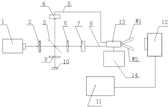
[0019] Example: such as figure 1 Shown is a fiber optic point diffraction device for three-dimensional vibration measurement, which includes a laser 1, a polarizer 2, a polarization beam splitter 3, a half-wave plate 6, a coupler I 4, a subwavelength aperture single-mode fiber 5, a quarter splitter One wave plate 9, mirror 10, coupler II 7, sub-wavelength aperture single-mode fiber II 8, high-speed CCD detector 12, measuring probe 13, computer 11. figure 1 The dotted lines with arrows in the middle represent optical paths, and the solid lines without arrows represent circuit connections. Laser 1 is a polarized laser. After passing through polarizer 2, the laser light generated by laser 1 is divided into two beams by polarizing beam splitter 3, the transmitted light p and the reflected light s. The transmitted light p passes through the half-wave plate 6 and then is coupled into the fiber coupler. II 7, then point diffraction spherical wavefront W2 is generated at the measurin...


PUM


Abstract

The invention discloses an optical fiber point diffraction device for three-dimensional vibration measurement and a measurement method. The device comprises a light path module, a measured object, a high-speed CCD detector and a computer, wherein the light path module is used for generating initial light and dividing the initial light into a plurality of beams of polarized light so as to send thepolarized light to an emission end; the measured object is connected with the emission end of the light path module; the high-speed CCD detector is used for acquiring interference information generated by a light signal at the emission end; and the computer is connected with the high-speed CCD detector and is used for processing the acquired information. The method comprises the steps of S01, enabling the high-speed CCD detector to acquire an interferogram generated by the emission of the light path module; S02, carrying out Fourier transformation on the interferogram to obtain a spectrogram;S03, processing the spectrogram to obtain a phase information map of the measured object and a real-time three-dimensional coordinate value of the measured object; and S04, carrying out sampling and processing calculation for multiple times to obtain the vibration condition of the measured object. The device and the method are capable of realizing the continuous dynamic measurement in the three-dimensional direction, and are high in measurement precision and small in interference suffered from the external factors.

Description

technical field [0001] The invention relates to the technical field of optical measurement, in particular to an optical fiber point diffraction device and a measurement method for three-dimensional vibration measurement. Background technique [0002] At present, there are mainly two methods to study the vibration of objects: one is to use sensors to directly receive vibration signals to study the vibration characteristics of objects, and the other is to use optical interference. However, although the method of using sensors to measure vibration is simple in structure and low in cost, the disadvantage is that the measurement range is limited to one-dimensional direction, and three-dimensional measurement cannot be realized, and the use of sensors is more susceptible to external interference, such as temperature, vibration, etc. etc. Another optical interferometry method can extract some signals that are difficult to extract better, but the defect is that the structure is comp...

Claims


Application Information

Patent Timeline
Patent Type & Authority Patents(China)
IPC IPC(8): G01H9/00
CPCG01H9/004
Inventor 王道档朱其幸孔明许新科赵军刘维郭天太
Owner CHINA JILIANG UNIV
Why Eureka
Try Eureka