Novel ring-on-ring biaxial bending strength test clamp and positioning cover thereof

A bending strength and testing fixture technology, applied in the direction of using a stable bending force to test material strength, strength characteristics, measuring devices, etc. The effect of preventing errors, fast alignment, and preventing sputtering everywhere

Pending Publication Date: 2019-08-23
SICHUAN UNIV
View PDF0 Cites 2 Cited by
  • Summary
  • Abstract
  • Description
  • Claims
  • Application Information

AI Technical Summary

Problems solved by technology

First of all, when installing the fixture and sample, it is required that the central axis positioning of the loading ring and the support ring be accurate to 0.5% of the diameter of the support ring, and the central axis positioning of the sample and the upper and lower rings should be accurate to 2% of the diameter of the support ring. If the center offset is too large, the stress distribution will be uneven, and the starting point of the fracture will always be located near the loading ring. In actual operation, due to the large error of manual calibration, it is impossible to accurately align the three, resulting in invalid fracture and time-consuming
And during the relative movement of the loading ring and the support ring, the sample is displaced, and the line or point contact stress and friction between the upper and lower rings and the sample will cause stress concentration, so that the stress of the sample is beyond the actual bending strength. lower fracture, resulting in inaccurate experimental results
In addition, due to the lack of a structure for accommodating the sample, the device is not easy to collect after the sample is broken, which is not convenient for later experiments

Method used


Image

  • Novel ring-on-ring biaxial bending strength test clamp and positioning cover thereof
  • Novel ring-on-ring biaxial bending strength test clamp and positioning cover thereof
  • Novel ring-on-ring biaxial bending strength test clamp and positioning cover thereof

Examples


Embodiment 1

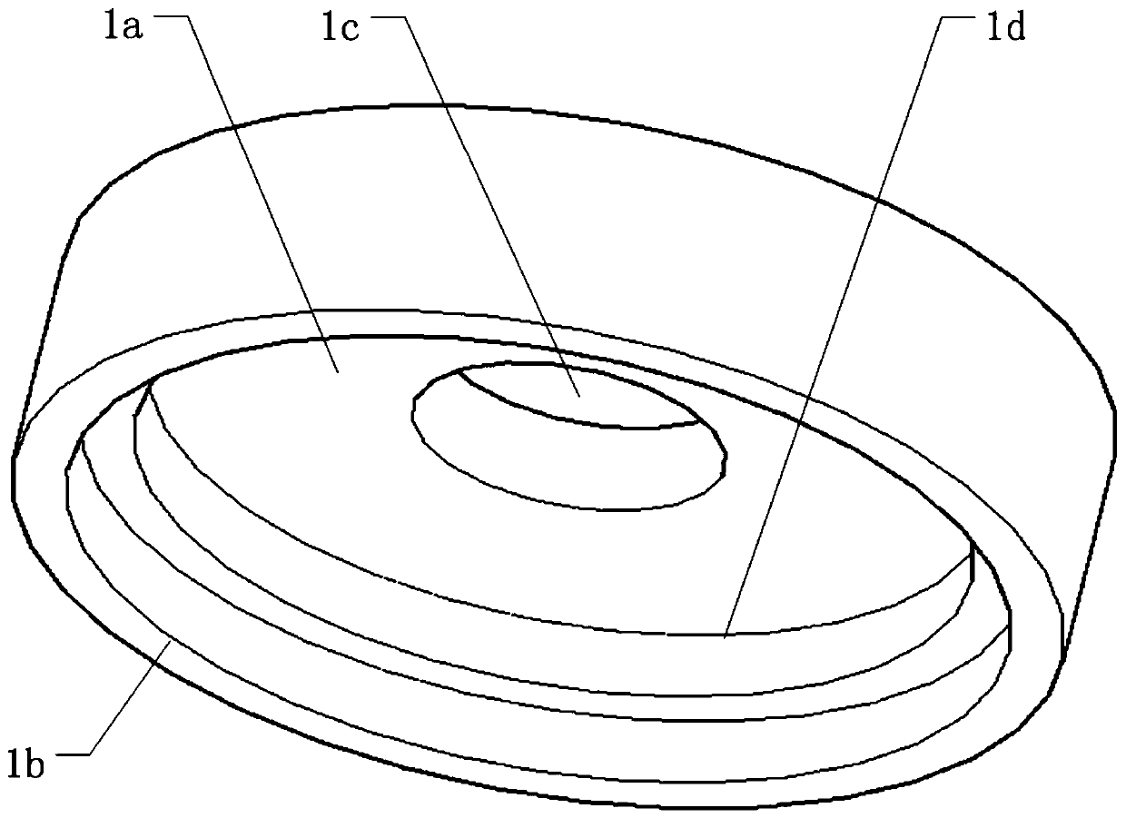
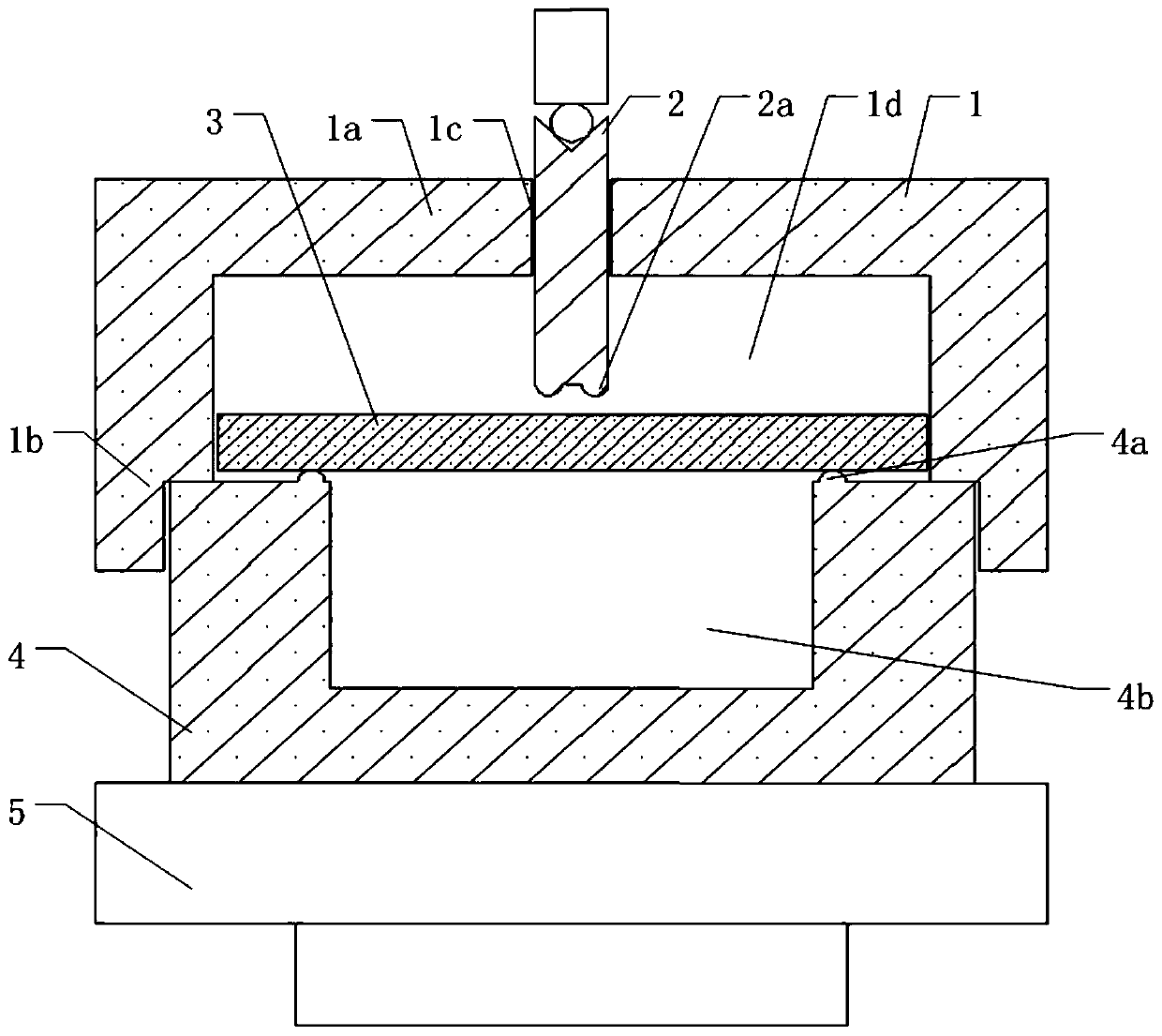
[0034] Such as figure 2 As shown, this embodiment discloses a positioning cover for a ring-on-ring biaxial bending strength test fixture, and the ring-on-ring biaxial bending strength test fixture includes a loading ring installation part with a loading ring 2a installed at the bottom 2. The support ring installation part 4 of the support ring 4a is installed on the top, and the two installation parts are arranged opposite to each other. The bottom of the positioning cover 1 is provided with an accommodating cavity 1d for accommodating the test sample 3, and the size of the accommodating cavity 1d corresponds to the test sample 3, so that the test sample 3 cannot move left and right after being placed in the accommodating cavity 1d. The bottom of the positioning cover 1 is designed with a mounting mechanism 1b for mounting the positioning cover 1 on the mounting part 4 of the support ring. Extending the direction of the top 1a of the positioning cover at the top of the chamb...

Embodiment 2

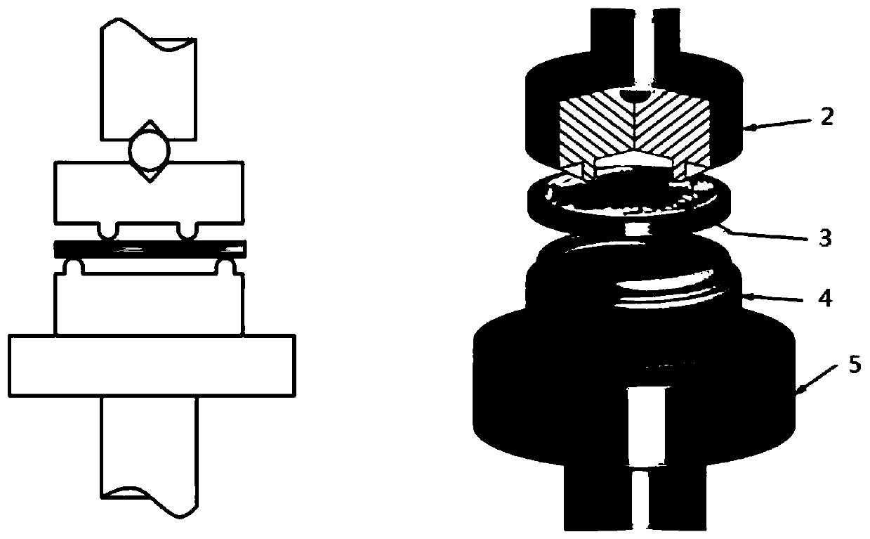
[0037]This embodiment discloses a novel ring-on-ring biaxial bending strength test fixture, which includes a loading ring installation part 2, a loading ring 2a, a support ring installation part 4, a support ring 4a and a positioning cover 1, and a loading ring installation part 2 is set opposite to the support ring installation part 4, the loading ring 2a is installed on the bottom of the loading ring installation part 2, the support ring 4a is installed on the top of the support ring installation part 4, and the positioning cover 1 is installed on the top of the support ring installation part 4 through the installation mechanism 1b. On the positioning cover 1, there is a channel 1c that allows the loading ring installation part 2 to pass through. The size of the channel 1c corresponds to the loading ring installation part 2. The loading ring installation part 2 is arranged in the channel 1c. The position of the channel 1c is designed It is: when the loading ring mounting part...

Embodiment 3

[0039] This embodiment discloses a novel ring-on-ring biaxial bending strength test fixture, which includes a loading ring installation part 2, a loading ring 2a, a support ring installation part 4, a support ring 4a and a positioning cover 1. The loading ring 2a is relatively The support ring 4a has a small diameter, the support ring installation part 4 is installed on the support rod 5, the loading ring installation part 2 is arranged opposite to the support ring installation part 4, the loading ring 2a is installed in the bottom middle of the loading ring installation part 2, and the support ring 4a is installed on In the middle of the top of the support ring installation part 4 , the positioning cover 1 is arranged on the support ring installation part 4 . A mounting mechanism 1b is designed around the bottom of the positioning cover 1 for stably mounting to the surroundings of the top of the loading ring mounting part 2 . In one embodiment, the installation mechanism 1b i...


PUM

PropertyMeasurementUnit
diameteraaaaaaaaaa

Abstract

The invention discloses a novel ring-on-ring biaxial bending strength test clamp and a positioning cover thereof. A containing cavity is formed in the bottom of the positioning cover, and the size ofthe containing cavity corresponds to a test sample; an installing mechanism is arranged at the bottom of the positioning cover; a channel is formed in the top of the positioning cover, and the size ofthe channel corresponds to the size of a loading ring installing part; the channel position is designed as follows: when the positioning cover is installed on a supporting ring installing part through the installing mechanism, the middle shaft of a loading ring is overlapped with the middle shaft of a supporting ring; the position of the containing cavity is designed as follows: when the positioning cover is installed on the supporting ring installing part through the installing mechanism, and the middle shaft of the containing cavity is overlapped with the middle shaft of the supporting ring. The clamp comprises the positioning cover, the supporting ring, the supporting ring installing part, the loading ring and the loading ring installing part. According to the positioning cover in theinvention, the middle shafts of the loading ring, the supporting ring and the test sample can be aligned rapidly and accurately, the test efficiency and the accuracy rate of the test result are improved; the clamp can be used for storing sample fragments and preventing the sample fragments from being sputtered.

Description

technical field [0001] The invention relates to a biaxial bending test tool assembly, in particular to a positioning cover in a ring-on-ring biaxial bending strength testing tool, and a novel ring-on-ring biaxial bending strength testing fixture comprising the positioning cover. Background technique [0002] Ring-on-ring biaxial bending test (ring-on-ring biaxial bending test) is a classic method to test the bending strength of structural ceramics. According to the ASTM standard, the fixture consists of a loading fixture consisting of a loading ring mounting part and a loading ring, and a supporting fixture consisting of a supporting ring mounting part and a supporting ring (such as figure 1 As shown), the test sample is positioned between the loading ring and the support ring, and the relative movement of the upper and lower rings in the vertical direction causes the sample to bend. The bending strength is the maximum stress when the sample bends and breaks between the uppe...

Claims


Application Information

Patent Timeline
Patent Type & Authority Applications(China)
IPC IPC(8): G01N3/04G01N3/20
CPCG01N3/04G01N3/20
Inventor 于海洋鲁雨晴楼雨欣张隽婧
Owner SICHUAN UNIV
Why Eureka
Try Eureka