Current type fault diagnosis apparatus and method for micro-vibration motor
A technology of fault diagnosis instrument and vibration motor, which is applied in vibration testing, motor generator testing, components of electrical measuring instruments, etc., can solve problems such as low detection efficiency, unrounded commutator segments, and abnormal commutation.
- Summary
- Abstract
- Description
- Claims
- Application Information
AI Technical Summary
Problems solved by technology
Method used
Image

Examples
Embodiment 1
[0051] Embodiment 1 Miniature Vibration Motor Current Type Fault Diagnosis Instrument
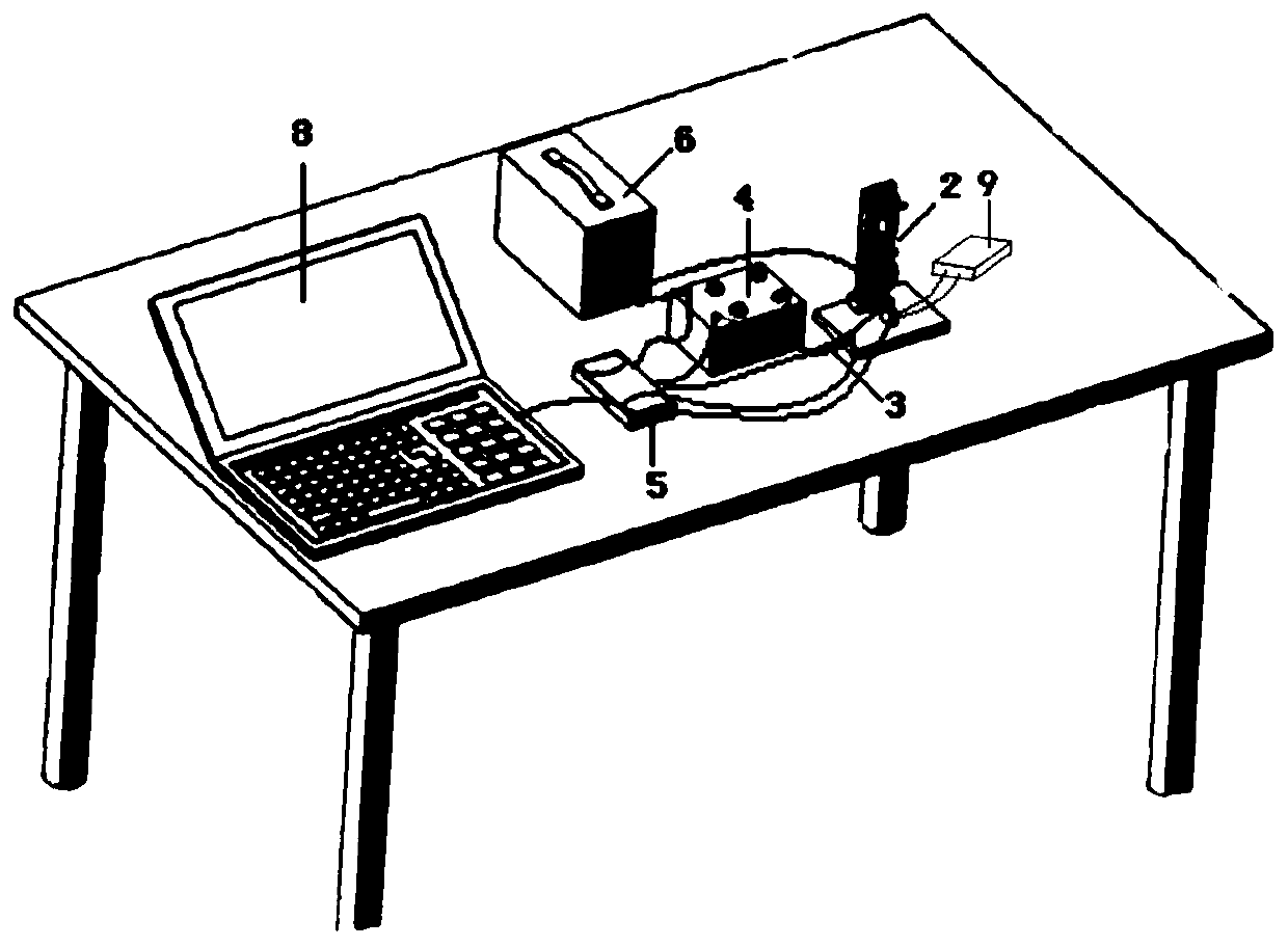
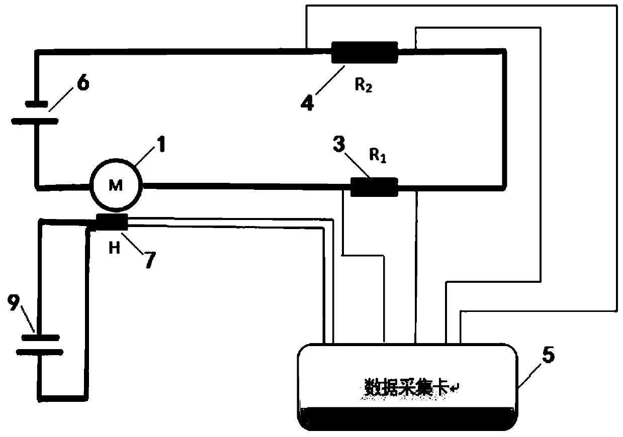
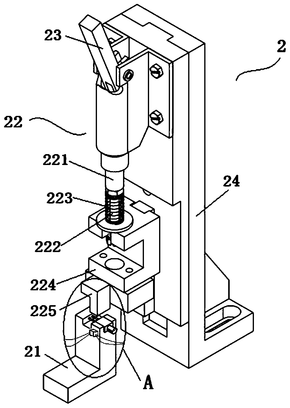
[0052] The miniature vibrating motor current type fault diagnosis instrument provided by this embodiment has a structure such as figure 1 and figure 2 As shown, it includes an installation mechanism 2 for installing and fixing the micro vibration motor 1 to be tested, a starting resistor R 1 3. Sampling resistor R 2 4. Data acquisition card 5, first power supply 6, hall sensor H 7, second power supply 9 and computer 8. When the type of the micro vibration motor to be tested is determined, adjust the first power supply voltage, the second power supply voltage, the sampling resistor R 2 , Data acquisition card (including acquisition rate and number of sampling points), and remain unchanged. Users can also adjust these parameters by themselves to meet the detection of the micro vibration motor to be tested under different working conditions.
[0053] The sampling resistor R used in this ...
Embodiment 2
[0059] Embodiment 2 Micro Vibration Motor Fault Detection
[0060] This embodiment provides a method for diagnosing a micro vibration motor fault using the above-mentioned current-type fault diagnostic instrument, including the following steps:
[0061] (1) Use the current-type fault diagnosis device to obtain the voltage signal of the sampling resistor and the magnetic pole signal of the micro-vibration motor, and use the voltage signal of the sampling resistor as a voltage characteristic signal representing the operation of the micro-vibration motor.
[0062] Place the micro-vibration motor 1 to be tested in the slot of the stage, and press and fix it by the damping and pressing mechanism. Install the connection methods in Example 1 for each component; then connect the first power supply 6 and the second power supply 9, and start the miniature vibration motor. When the data acquisition card 5 collects the starting resistance R 1 When the voltage signal of 3, start to coll...
PUM
 Abstract
Description
Claims
Application Information
 - R&D
- Intellectual Property
- Life Sciences
- Materials
- Tech Scout
- Unparalleled Data Quality
- Higher Quality Content
- 60% Fewer Hallucinations
Browse by: Latest US Patents, China's latest patents, Technical Efficacy Thesaurus, Application Domain, Technology Topic, Popular Technical Reports.
© 2025 PatSnap. All rights reserved.Legal|Privacy policy|Modern Slavery Act Transparency Statement|Sitemap|About US| Contact US: help@patsnap.com