Multi-sound field interfered acoustic levitation device and sound filed switching method

A technology of acoustic levitation and sound field, which can be used in measurement devices, re-radiation of sound waves, and re-radiation by use of sound waves. low effect

Active Publication Date: 2019-08-23
SOUTH CHINA UNIV OF TECH
View PDF11 Cites 6 Cited by
  • Summary
  • Abstract
  • Description
  • Claims
  • Application Information

AI Technical Summary

Problems solved by technology

The traditional resonant standing wave field can use high-power transducers to suspend heavier particles, but it is very sensitive to the distance between the vibrators and it is difficult to manipulate the particles; the non-resonant acoustic levitation technology suspends the position

Method used


Image

  • Multi-sound field interfered acoustic levitation device and sound filed switching method
  • Multi-sound field interfered acoustic levitation device and sound filed switching method
  • Multi-sound field interfered acoustic levitation device and sound filed switching method

Examples


Embodiment 1

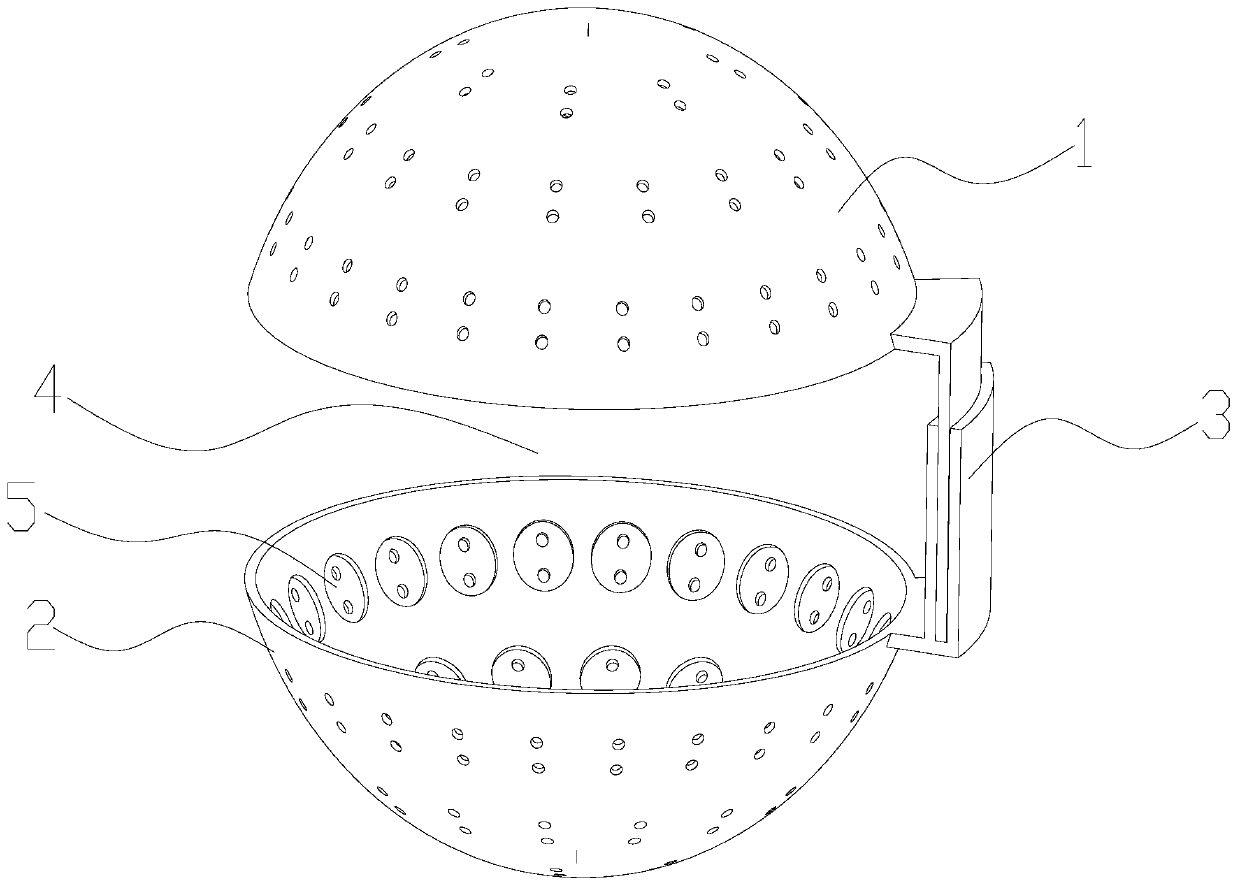
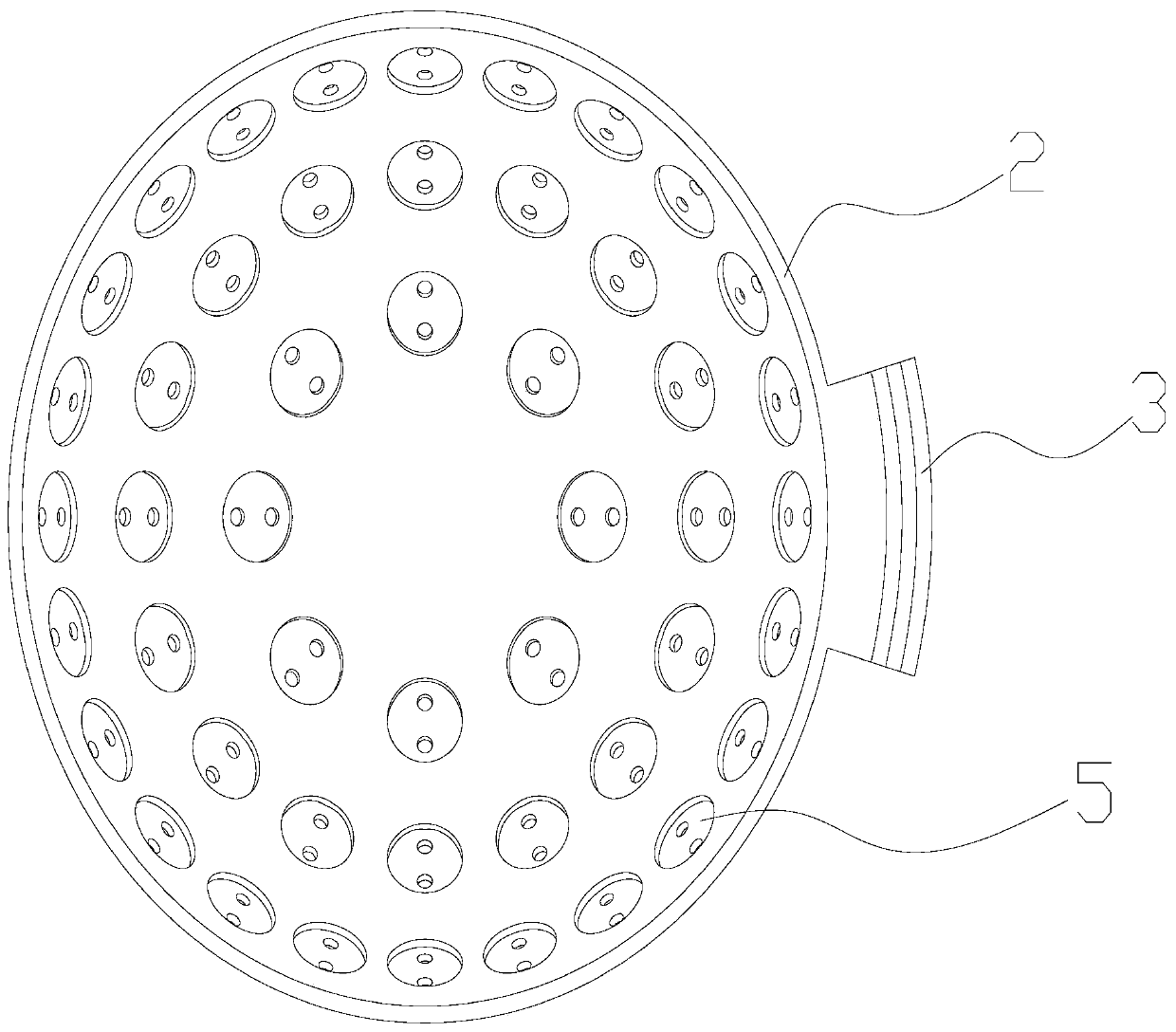
[0027] Such as figure 1 with figure 2 As shown, the present embodiment is a multi-sound field interference acoustic levitation device, including a single-chip microcomputer, a drive motor module, a power supply module, a controller, an upper casing 1, a lower casing 2, a connecting part 3 and sixteen ultrasonic emission areas;

[0028] Such as figure 1 with figure 2 As shown, the upper shell and the lower shell are in the shape of a hemispherical shell respectively, the upper shell and the lower shell are arranged opposite and parallel, the connecting part connects the upper shell and the lower shell, and the upper shell, the lower shell and the connecting part 3D printing is adopted, and the upper shell and the lower shell are arranged at intervals to form a suspension space 4, and a plurality of mounting holes 5 are respectively provided on the upper shell and the lower shell.

[0029] Such as figure 1 with figure 2 As shown, eight ultrasonic emitting areas are distr...

Embodiment 2

[0039] The difference between this embodiment and Embodiment 1 is that the above-mentioned multi-sound field interference acoustic levitation device is used as a switching method of the vortex field. The upper casing is energized, and the initial phases of the eight ultrasonic emission areas on the upper casing are gradually shifted toward the clockwise direction. Incremental, for example, the initial phases of ↑Ⅰ, ↑Ⅱ, ↑Ⅲ, ↑Ⅳ, ↑Ⅴ, ↑Ⅵ, ↑Ⅶ, ↑Ⅷ are 0, Π / 4, Π / 2, 3Π / 4, Π, 5Π / 4 . The initial phases in the clockwise or counterclockwise direction gradually increase, for example, the initial phases of ↓Ⅰ, ↓II, ↓Ⅲ, ↓IV, ↓Ⅴ, ↓Ⅵ, ↓Ⅶ, ↓Ⅷ are 0, Π / 4, Π / 2, 3Π / 4, Π, 5Π / 4, 3Π / 2, 7Π / 4, the sum of the initial phase changes of the eight ultrasonic emission areas on the lower shell is 2π, that is, a topological charge For a sound field with a degree of 1, when the initial phase change direction of the eight ultrasonic emission areas on the lower shell is the same as the initial phase change dire...

Embodiment 3

[0043] The difference between this embodiment and embodiment 1 is that, as Figure 4 As shown, the two points A and B represent two point sound sources with opposite phases. The length of the AC line segment is a, the length of the BC line segment is b, and the length of OC is r. When a-b=λ / 2 is satisfied, and λ is the wavelength of the sound wave, C The point is the first-level main-level bright fringe, and OC can be approximately regarded as 0 sound pressure. Through this principle, the phase difference between adjacent ultrasonic emission areas is π, and a large central zero-sound pressure area can be constructed by arranging in a circle to suspend large objects.

[0044] Set the initial phases of the eight ultrasonic emitting areas on the upper shell to gradually increase by π in the clockwise direction, for example, the initial phases of ↑Ⅰ, ↑Ⅱ, ↑Ⅲ, ↑Ⅳ, ↑Ⅴ, ↑Ⅵ, ↑Ⅶ, ↑Ⅷ 0, π, 2π, 3π, 4π, 5π, 6π, 7π, the sum of the initial phase changes of the eight ultrasonic emission area...


PUM


Abstract

The invention discloses a multi-sound field interfered acoustic levitation device and a sound filed switching method. The device comprises a microcontroller, a driving motor module, a power module, acontroller, an upper shell, a lower shell, a connection part and a plurality of ultrasonic wave emission areas. The upper shell and the lower shell are opposite and are set in parallel. The upper shell and the lower shell are connected by the connection part. The upper shell and the lower shell are spaced to form a levitation space. The plurality of ultrasonic wave emission areas are set on the upper shell and the lower shell and are distributed according to an array. Each ultrasonic wave emission area comprises a plurality of ultrasonic wave emitters. The controller outputs a signal to the microcontroller. The microcontroller receives the signal and outputs a square wave signal to the driving motor module. The driving motor module drives the plurality of ultrasonic wave emission areas towork. An initial phase of each ultrasonic wave emission area is further adjusted through change of the signal output by the controller, and curl of a sound field is adjusted.

Description

technical field [0001] The invention relates to the technical field of ultrasonic array levitation, in particular to a multi-sound field interference acoustic levitation device and a sound field switching method. Background technique [0002] Acoustic levitation is a nonlinear effect under the condition of high sound intensity. At present, the basic principle is to use the interaction between the acoustic standing wave and the object to generate a vertical levitation force to overcome the weight of the object, and at the same time generate a horizontal positioning force to move the object Fixed at the sound pressure node. [0003] Acoustic levitation generating devices are divided into resonance type and non-resonance type. The traditional resonant standing wave field can use high-power transducers to suspend heavier particles, but it is very sensitive to the distance between the vibrators and it is difficult to manipulate the particles; the non-resonant acoustic levitation...

Claims


Application Information

Patent Timeline
IPC IPC(8): G01S15/88
CPCG01S15/88
Inventor 范铭铭谢越彭健新金雪晴叶晓靖
Owner SOUTH CHINA UNIV OF TECH
Why Eureka
Try Eureka