Method and system of guiding robot to be recharged automatically
An automatic charging and guiding system technology, applied in control/adjustment systems, instruments, current collectors, etc., can solve the problems of long time consumption, high equipment configuration requirements, large errors, etc., and achieve the effect of low cost and improved guiding efficiency
- Summary
- Abstract
- Description
- Claims
- Application Information
AI Technical Summary
Problems solved by technology
Method used
Image
Examples
Embodiment 1
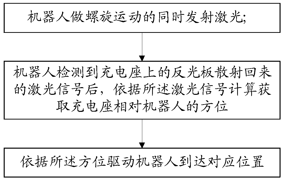
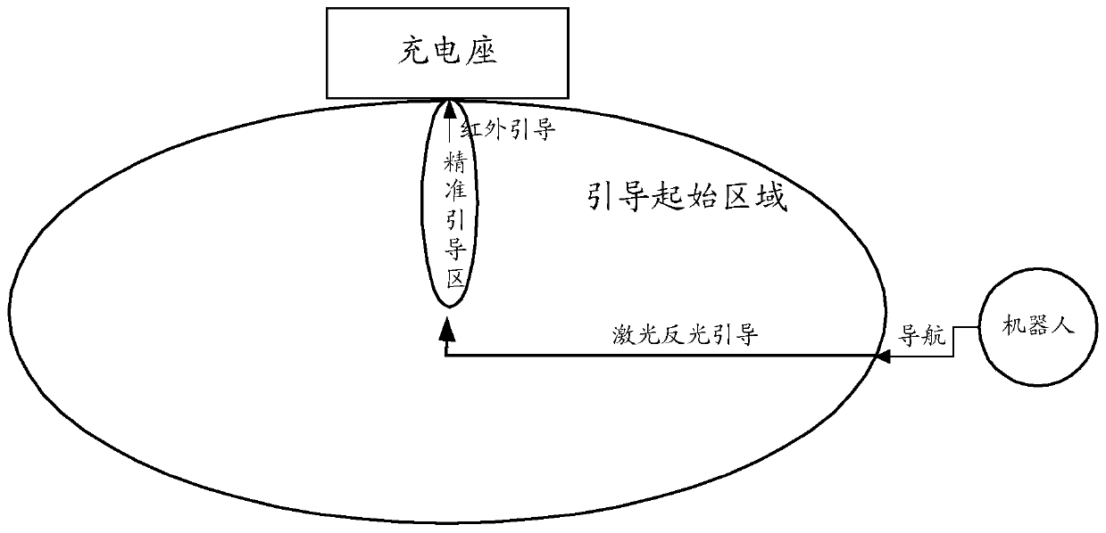
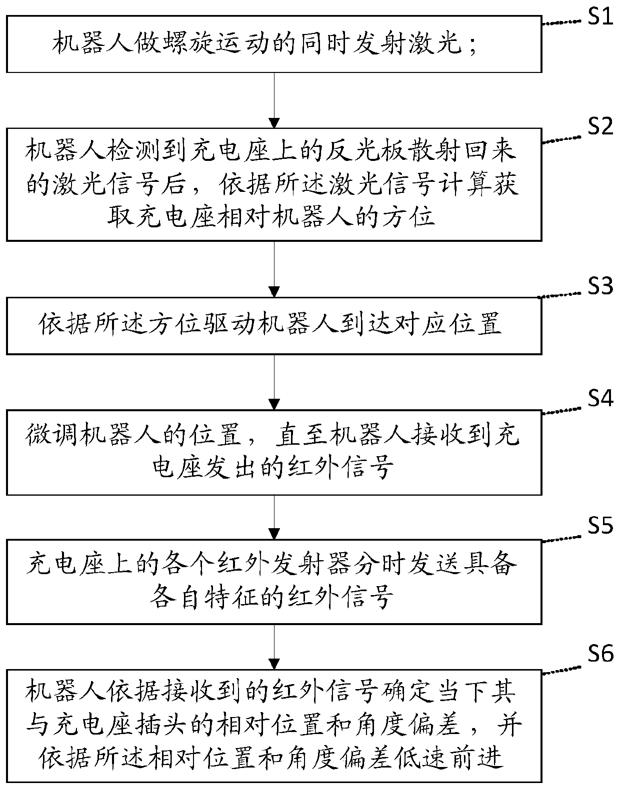
[0067] Please refer to Figure 2 to Figure 5 , this embodiment provides a robot automatic charging guidance method, which can guide the difficulty and significantly improve the guidance efficiency.
[0068] The method of this embodiment is realized based on the robot automatic charging guidance system, please refer to Figure 4 and Figure 5 , the system includes a robot 1 and a charging stand 2; the robot 1 is provided with a laser emitting module 13, a laser detection module 14, an infrared receiving module 12 and a charging control module 11, and the laser emitting module 13, the laser detection module 14 and the infrared The receiving module 12 is connected with the charging control module 11 respectively; the infrared emitting module 22 made of at least two infrared emitters, at least two laser reflectors ( Figure 5 In the first laser reflector 24 and the second laser reflector 25) and the charging output control module 21, more than two infrared emitters are arranged ...
Embodiment 2
[0089] This embodiment is further expanded on the basis of the first embodiment to improve the efficiency of the robot identifying the charging base based on the laser reflector. The same parts will not be repeated, and the difference is that, before step S1 of the first embodiment, a process of navigating and locating the charging stand is also included.
[0090] Specifically, the navigation and positioning charging stand process includes:
[0091] S01: The robot generates a navigation path with a preset distance from the self-positioning information to the charging stand positioning information according to its own positioning information and the preset charging stand positioning information.
[0092] Wherein, the positioning information of the robot itself is acquired by the navigation and positioning module on it, and the positioning information of the charging stand is preset and can be set through the client, such as specifying the position of the charging stand on the m...
Embodiment 3
[0097] This embodiment corresponds to Embodiment 2, and provides a robot automatic charging guidance system, please refer to Figure 4 and Figure 5 , including: robot 1 and charging stand 2;
[0098] The charging stand 2 includes more than two laser reflective plates (the first laser reflective plate 24 and the second laser reflective plate 25 in the figure) surrounding the charging stand, and more than two laser reflective plates surrounding the charging stand. Infrared emitter (constitutes the infrared emission module 22 in the figure); Also includes charging output control module 21 and robot identification module 23;
[0099] Each of the reflectors is used to reflect and scatter the laser signal after receiving the laser light emitted by the robot;
[0100] Each of the infrared emitters is used to send infrared signals with their own characteristics in time-sharing; specifically, the control signal of the charging output control module will be obtained, and an infrared ...
PUM
 Abstract
Description
Claims
Application Information
 - R&D
- Intellectual Property
- Life Sciences
- Materials
- Tech Scout
- Unparalleled Data Quality
- Higher Quality Content
- 60% Fewer Hallucinations
Browse by: Latest US Patents, China's latest patents, Technical Efficacy Thesaurus, Application Domain, Technology Topic, Popular Technical Reports.
© 2025 PatSnap. All rights reserved.Legal|Privacy policy|Modern Slavery Act Transparency Statement|Sitemap|About US| Contact US: help@patsnap.com


