Blade wheel for a sewage pump

Inactive Publication Date: 2008-04-24
KEENER ROBERT M
View PDF5 Cites 2 Cited by
  • Summary
  • Abstract
  • Description
  • Claims
  • Application Information

AI Technical Summary

Benefits of technology

[0007]A main objective of the present invention is to provide a blade wheel that comprises at least three types of curved blades in different heights radially arranged to im

Problems solved by technology

Because the multiple curved blades 12 are the same in height, the upper blade wheel has insufficient guiding efficiency.
When the curved blades 12 can not catch the precipitation sufficiently, the grinded precipitation

Method used


Image

  • Blade wheel for a sewage pump
  • Blade wheel for a sewage pump
  • Blade wheel for a sewage pump

Examples


Embodiment Construction

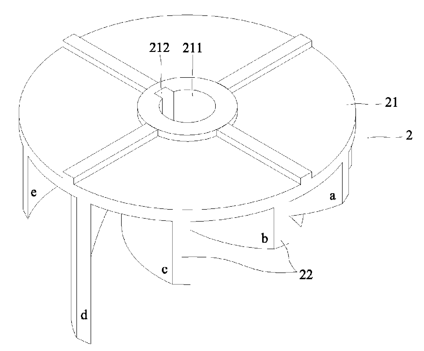
[0022]A blade wheel for a sewage pump in accordance with the present invention comprises a top plate and multiple curved blades radially attached to the top late. The top plate is adapted to perpendicularly combine with a main shaft of a motor and has a shaft hole with a slit at a center on the top plate. The multiple curved blades are integrally formed on a bottom face of the top plate and have at least three different heights. By attaching the curved blades in different heights, the precipitation can be sufficiently guided into a sewage pump for chopping and flung out of a sewage tank 4.

[0023]With reference to FIGS. 6, 7 and 8, a preferred embodiment of the blade wheel 2 for a sewage pump 3 comprises a top plate 21 and multiple curved blades 22 radially formed on the top plate 21.

[0024]The top plate 21 is a round board with a center and adapted to perpendicularly combine with a main shaft 311 on a motor 31 as shown in FIGS. 3 to 5. A shaft hole 211 with a slit 212 is defined at th...


PUM


Abstract

A blade wheel for a sewage pump has a top plate and multiple curved blades radially attached to the top late. The top plate is adapted to perpendicularly combine with a main shaft of a motor and has a shaft hole with a slit at a center on the top plate. The multiple curved blades are integrally formed on a bottom face of the top plate and have at least three different heights. By attaching the curved blades in different heights, the precipitation can be sufficiently guided into a sewage pump for chopping and flung out of sewage tank.

Description

BACKGROUND OF THE INVENTION[0001]1. Field of the Invention[0002]The present invention relates to a blade wheel for a sewage pump, and more particularly to a blade wheel that enables to guide precipitation in the sewage into a sewage pump for chopping and to efficiently discharge the sewage.[0003]2. Description of Related Art[0004]A conventional sewage pump in accordance with the prior art is connected with a motor by a main shaft and has a grinding wheel, a lower blade wheel and a upper blade wheel sleeving on the main shaft in sequence from inside to outside. When the motor actuates, the grinding wheel, the lower blade wheel and the upper blade wheel are driven to rotate by the main shaft. Moreover, rotation of the grinding wheel, the lower blade wheel and the upper blade wheel generate current to guide the precipitation into a lower base. When the precipitation passes an entrance on the lower base, the grinding wheel grinds the precipitation. When the grinded precipitation is guid...

Claims


Application Information

Patent Timeline
IPC IPC(8): B64C11/00
CPCF04D7/045F04D29/2288F04D29/225
Inventor KEENER, ROBERT M.
Owner KEENER ROBERT M
Why Eureka
Try Eureka