Supercharge Your Innovation With Domain-Expert AI Agents!

A Low-Frequency High-Performance Impedance Transformer

An impedance converter, a high-performance technology, is applied in the direction of waveguide devices, antenna grounding switch structure connection, electrical components, etc., which can solve the problems of large RF output impedance error and affecting output power, etc., to reduce steps and improve work Efficiency, increase the effect of bypass lightning protection

Active Publication Date: 2021-03-12
CHENGDU ZHONGYA TONGMAO TECH
View PDF4 Cites 0 Cited by
  • Summary
  • Abstract
  • Description
  • Claims
  • Application Information

AI Technical Summary

Problems solved by technology

[0004] However, the final RF output impedance error of the traditional impedance converter is relatively large, which affects the output power

Method used


Image

  • A Low-Frequency High-Performance Impedance Transformer
  • A Low-Frequency High-Performance Impedance Transformer
  • A Low-Frequency High-Performance Impedance Transformer

Examples


Embodiment 1

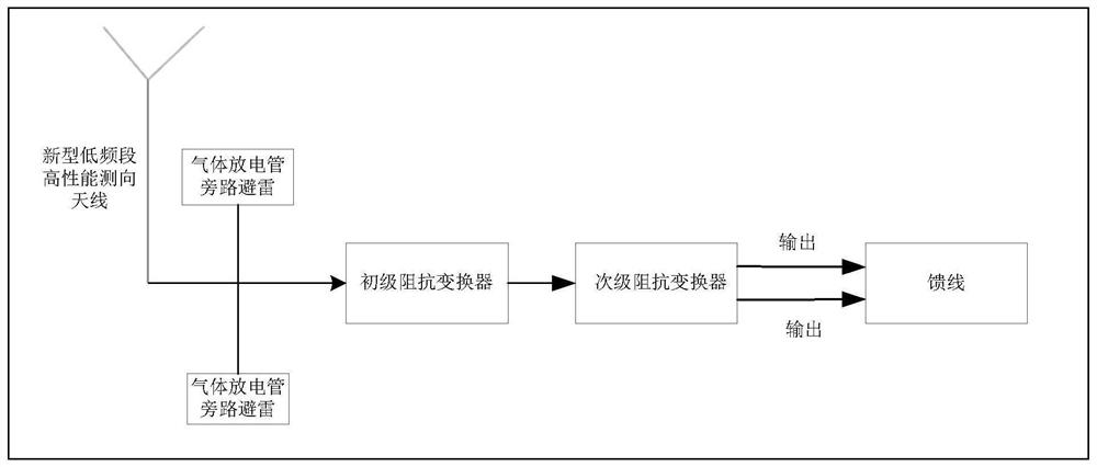
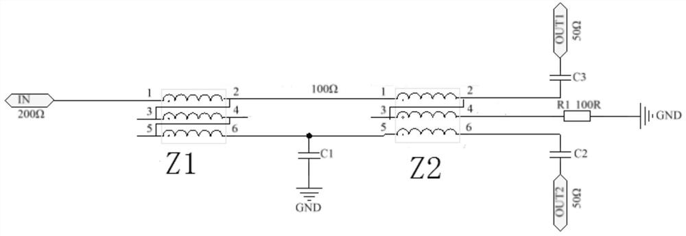
[0034] Please refer to figure 1 , a low-frequency band high-performance impedance converter, connected between the antenna output end and the feeder input end, used to transform the impedance of the antenna output end into an impedance equal to the feeder input end, the antenna output end is an unbalanced end, The input end of the feeder is a balanced end, which is characterized in that it includes a primary impedance variable and a secondary impedance variable connected to each other, the input of the primary impedance variable is connected to the antenna output, and the secondary impedance variable The output end is connected to the input end of the feeder. Both the primary impedance variable and the secondary impedance variable are twisted with three transmission lines. The primary impedance variable performs a processing on the impedance of the unbalanced end according to the preset impedance ratio. The set impedance ratio performs secondary processing on the impedance out...

Embodiment 2

[0038] Please refer to Figure 5 , this embodiment is further improved on the basis of Embodiment 1, the primary impedance variable and the secondary impedance variable are respectively detachably connected to the radio frequency printed board 1, and different positions on the radio frequency printed board 1 are respectively connected to Fastener 2. The components on the primary impedance variable transformer and the secondary impedance variable transformer are connected with different fasteners 2 to adjust the position of the components. The advantage of this method is that it can increase the debugging position of components, and the variable variable and the radio frequency printed board 1 are preferably integrally fixed in the housing by multiple stainless steel screws, and the traditional variable variable is suspended and welded, and the grounding is more effective.

Embodiment 3

[0040] Please refer to figure 1 , this embodiment is further improved on the basis of Embodiment 1, the input end of the primary impedance variable transformer is also connected to the gas discharge tube. The traditional variable transformer has no lightning protection capability for the time being, but the improved new variable variable transformer can bypass lightning protection by adding a gas discharge tube at the input end, which greatly replaces the reliability of the variable variable transformer.


PUM


Abstract

The invention discloses a low-frequency high-performance impedance converter, relates to an impedance matching technology, and solves the problem that the final radio frequency output impedance error of the traditional impedance converter is large and affects the output power. The present invention includes a primary impedance variator and a secondary impedance variator connected to each other, the input end of the primary impedance variator is connected to the antenna output end, the output end of the secondary impedance variator is connected to the feeder input end, and the primary impedance variator The primary impedance variable and the secondary impedance variable are both twisted with three transmission lines. The primary impedance variable processes the impedance of the unbalanced end according to the preset impedance ratio. The secondary impedance variable compares the output of the primary impedance variable according to the preset impedance ratio. The impedance is subjected to secondary processing and output to the balanced terminal. The invention has the advantages of finer adjustment of the final radio frequency output impedance, shortened product production cycle, improved work efficiency and the like.

Description

technical field [0001] The invention relates to an impedance matching technology, in particular to a low-frequency high-performance impedance converter. Background technique [0002] In radio frequency circuits, problems such as the connection between different transmission lines, the connection between different components, and the connection between the antenna and the feeder are often encountered. If it is a direct connection, reflection will inevitably occur and affect power transmission. Therefore, it is necessary to insert a matching network between the connection points to achieve impedance matching and ensure power transmission without reflection. [0003] In addition, in order to maximize the output power of the signal source, it is also desired that the output impedance of the external circuit and the source impedance achieve conjugate matching. Therefore, a matching network is usually required between the external circuit and the signal source. [0004] However, ...

Claims


Application Information

Patent Timeline
Patent Type & Authority Patents(China)
IPC IPC(8): H01P5/00H01P5/10H01Q1/50
CPCH01P5/00H01P5/10H01Q1/50
Inventor 郝温利王煜川
Owner CHENGDU ZHONGYA TONGMAO TECH
Features
  • R&D
  • Intellectual Property
  • Life Sciences
  • Materials
  • Tech Scout
  • Unparalleled Data Quality
  • Higher Quality Content
  • 60% Fewer Hallucinations
Learn More