a busbar

A busbar and unified technology, applied in the field of auto parts, can solve the problems of unbearable load current, low space utilization rate, and small number of outgoing busbars, so as to achieve increased space utilization rate, high space utilization rate, and convenient simultaneous The effect of side wiring

Active Publication Date: 2020-09-11
FUYANG DUOBAO ELECTRONICS
View PDF1 Cites 0 Cited by
  • Summary
  • Abstract
  • Description
  • Claims
  • Application Information

AI Technical Summary

Problems solved by technology

[0005] The purpose of the present invention is to provide a busbar, using a busbar frame, a first lead-out busbar at a first height position, a second lead-out busbar at a second height position; a third lead-out busbar at a third height position And the first star point branch row is located in the first installation groove and is lower than the second height position of the second lead-out busbar to form a fourth height position, which is used to separate at least four height positions, and three or more lead-outs can be arranged Busbar: Solve the defects that the existing lead-out busbars are small in number, low in space utilization, and unable to withstand excessive load current

Method used


Image

  • a busbar
  • a busbar
  • a busbar

Examples


Embodiment 1

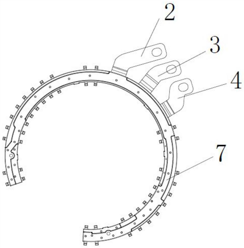
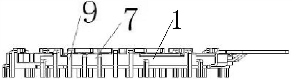
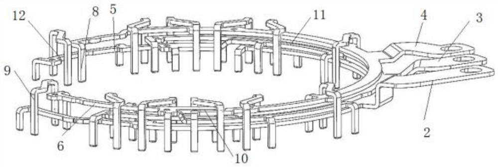
[0041] Such as figure 1 , figure 2 , image 3 , Figure 4 , Figure 5 , Figure 6 , Figure 7 , Figure 8 , Figure 9 and Figure 10 As shown, a busbar provided by the present invention includes: a busbar frame 1 integrally formed by injection molding, a first lead-out busbar 2, a second lead-out busbar 3, a third lead-out busbar 4, and a first star point branch bar 5. The second star-point branch bar 6 and the injection-molded fixing plate 7; the injection-molding fixing plate is coated on the first lead-out busbar, the second lead-out busbar, the third lead-out busbar, the first star-point branch bar and the The outer surface of the second astral branch. The first lead-out busbar, the second lead-out busbar, the third lead-out busbar, the first star point branch bar and the second star point branch bar are all provided with wiring sockets 8, and the tops of the wiring sockets all face The same side of the busbar; the bottom ends of the wiring strips are separated ...


PUM


Abstract

The invention provides a busbar. The busbar includes a busbar frame formed by injection molding, a first lead-out busbar which is mounted on one side of the busbar frame and located at the first height position, a second lead-out busbar which is injection-fixed on the busbar frame and located at the second height position, a third lead-out busbar which is mounted on a side of the busbar frame awayfrom the first lead-out busbar and located at the third height position, and a first star-point branch bar including a first side bar and a second side bar connecting with the first side bar, whereinthe first side bar is located at an inner side of the busbar frame and is at the same level position as the first lead-out busbar, the second side bar is lower than the second height position of thesecond lead-out busbar, and the fourth height position is formed. The busbar is advantaged in that the space utilization rate is higher, problems of small quantity and the lower space utilization rateof lead-out busbars in the prior art are solved, and the over-large load current can not be borne.

Description

technical field [0001] The invention relates to the field of auto parts, in particular to a busbar. Background technique [0002] At present, the busbar, as the core device of current conduction in the controller, often faces the defects of a small number of lead-out busbars (only 1 to 2 pieces), low space utilization, and inability to withstand excessive load current. [0003] In the prior art, just like the patent document 1: CN201820465006.X, this invention patent provides a busbar, a busbar assembly, a controller and a vehicle, a busbar, and the busbar includes a plate-shaped The structure of the busbar body, the busbar body is bent to form a groove. The groove is formed as a U-shaped groove and is used as a capacitor installation groove, and the side wall of the U-shaped groove is provided with a capacitor positive installation part and a capacitor negative installation part; and / or the busbar body includes a laminated A positive conductive layer and a negative conduc...

Claims


Application Information

Patent Timeline
Patent Type & Authority Patents(China)
IPC IPC(8): H02G5/02
CPCH02G5/02
Inventor 潘国平
Owner FUYANG DUOBAO ELECTRONICS
Why Eureka
Try Eureka