
Small differential electric field activated uhf RFID device

A differential and electric field technology, applied in the field of UHF RFID devices activated by small differential electric fields, can solve the problems of limited practicability, high failure rate, user damage, etc., and achieve the effect of improving recyclability, improving survivability, and being easy to manufacture.

Pending Publication Date: 2019-08-23
艾利丹尼森零售信息服务公司
View PDF7 Cites 0 Cited by
  • Summary
  • Abstract
  • Description
  • Claims
  • Application Information

AI Technical Summary

Problems solved by technology

[0005] However, smart tags do have certain disadvantages
For example, smart marks are more susceptible to physical damage than optical barcodes
Smart tags are also somewhat more expensive to use than optical barcodes
While optical barcode markings can be printed using traditional marking printers or even standard consumer grade inkjet printers, smart markings must be printed using a more specialized printer and will have a slightly higher failure rate (typically around 5%) when printing
Finally, smart marks are larger and more prominent than optical barcode marks, limiting their usefulness in some applications
For example, "RFID tickets" typically have a large embedded antenna that spans a large portion of the ticket, which means that the user may run the risk of damaging the ticket and making it unusable due to it being folded

Method used


Image

  • Small differential electric field activated uhf RFID device
  • Small differential electric field activated uhf RFID device
  • Small differential electric field activated uhf RFID device

Examples


Embodiment Construction

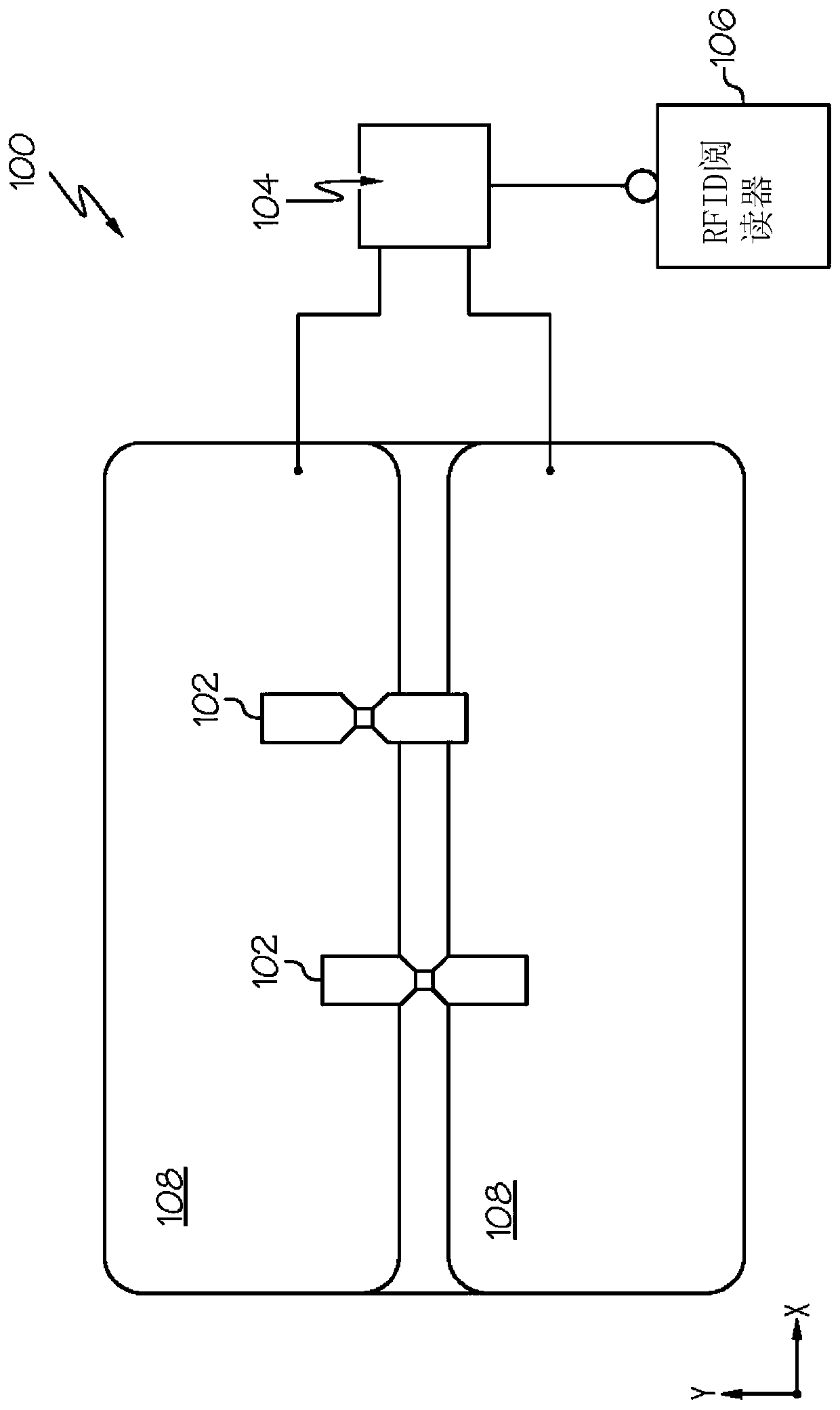
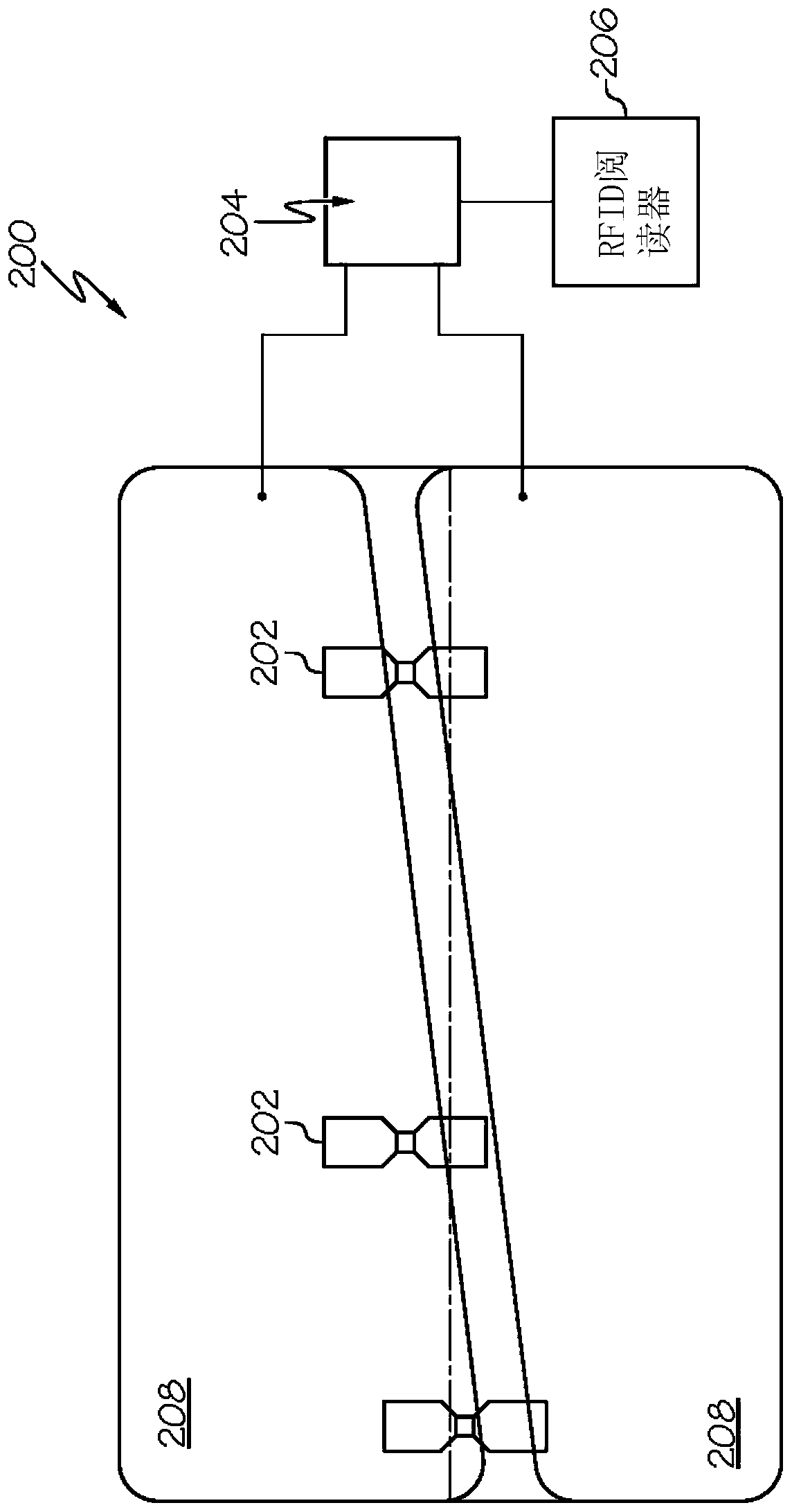
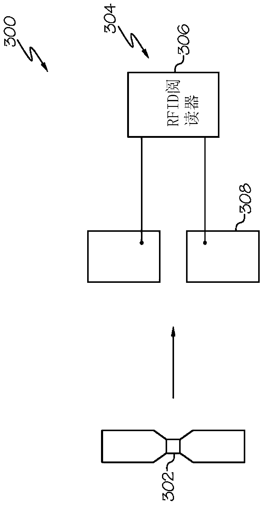
[0018] Aspects of the invention are disclosed in the following description of specific embodiments of the invention and the associated drawings. Alternative embodiments may be devised without departing from the spirit or scope of the invention. Additionally, well-known elements of exemplary embodiments of the invention will not be described in detail or will be omitted so as not to obscure the relevant details of the invention. In addition, in order to facilitate the understanding of the description of several terms used in this paper, they will be discussed below.

[0019] As used herein, the word "exemplary" means "serving as an example, instance, or illustration." The embodiments described herein are not limiting, but illustrative only. It should be understood that the described embodiments are not necessarily to be construed as preferred or advantageous over other embodiments. Furthermore, the terms "embodiments of the invention", "an embodiment" or "invention" do not r...


PUM


Abstract

A small differential-electric-field-activated UHF RFID device. Such a device may be small and easy to manufacture, improving the viability of incorporating RFID technology into articles like tickets,cards, and tokens. Such a device may also be small and inexpensive enough to allow for redundant RFID chips to be placed on an article, improving the survivability of an RFID-enabled article. Such a device may also reduce the amount of metal or plastic that is used in order to create an article such as a smart ticket or card, improving recyclability.

Description

[0001] Cross References to Related Applications [0002] This application claims priority to and benefit of U.S. Provisional Patent Application No. 62 / 444,823, filed January 11, 2017, the entire contents of which are incorporated herein by reference. Background technique [0003] A "smart label", also called a "smart label", is a printed coded label that contains an extremely flat configured transponder as an inlay inside the label. These transponders typically include a chip, antenna and bonding wire. [0004] In many processes, such as in logistics and transportation, "smart tags" or "smart labels" have replaced more traditional optical barcodes, as well as 2D barcodes, QR codes, etc., as the key means by which items can be identified and tracked. Automation of such optical encodings is limited in the appropriate distance for read success, and often requires manual manipulation to bring the code into the scanner's field of vision (or, alternatively, requires the use of a sc...

Claims


Application Information

Patent Timeline
IPC IPC(8): G06K19/077
CPCG06K19/07749G06K19/07786G06K7/10366G06K19/18G06K7/10158
Inventor I.J.福斯特
Owner 艾利丹尼森零售信息服务公司
Features
  • Generate Ideas
  • Intellectual Property
  • Life Sciences
  • Materials
  • Tech Scout
  • Unparalleled Data Quality
  • Higher Quality Content
  • 60% Fewer Hallucinations
Learn More