First aid equipment and method for light modulation status information

A technology of state information and first aid equipment, applied in electrotherapy, treatment, cardiac defibrillator, etc., can solve the problems of inability to effectively form equipment status, difficult rapid output of emergency equipment, continuous display, etc.

Active Publication Date: 2021-04-27
深圳市联普医疗科技有限公司
View PDF1 Cites 0 Cited by
  • Summary
  • Abstract
  • Description
  • Claims
  • Application Information

AI Technical Summary

Problems solved by technology

[0004] The purpose of the present invention is to provide emergency equipment and methods for lighting modulation state information, so as to solve the problem that the existing emergency equipment is difficult to easily and effectively realize the rapid output of self-test results, and the equipment cannot effectively form a continuous display of equipment status after power failure question

Method used


Image

  • First aid equipment and method for light modulation status information
  • First aid equipment and method for light modulation status information
  • First aid equipment and method for light modulation status information

Examples


Embodiment 1

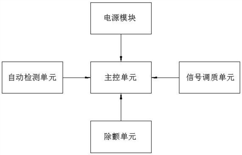
[0046] The defibrillator 1 is in the working state, or the defibrillator battery 17 is in an electrified state, and the coil on the energized coil 27 is energized under the conduction of the defibrillator battery 17, thereby generating an induced magnetic field, and generating a magnetic field to the magnetic conductive plate 29. Magnetic attraction, so that the magnetic conductive plate 29 is engaged with the first power conductive plate 28, and the first power conductive plate 28 is connected to the defibrillator battery 17, thereby forming a conductive switch 21 and the defibrillator battery 17. through, so that the single-chip microcomputer 20 is driven by the power supply of the defibrillator battery 17;

Embodiment 2

[0048] The same as the internal structure of Embodiment 1, the defibrillator 1 is in the shutdown state, or the defibrillator battery 17 is in a de-energized state, and there is no current passing through the energized coil 27, and the repulsive force of the magnetic field or the rebound and limitation of the insulating spring 33 are used to make The mobile conductive plate 32 is engaged with the second power conductive plate 31, and the second power conductive plate 31 is connected to the backup battery 19, so that the backup battery 19 is connected to the conductive switch 21. At this time, the single-chip microcomputer 20 is powered by the backup battery 19 drive.

[0049] In the present invention, preferably, there are two insulating connecting rods 35 , and the two insulating connecting rods 35 are symmetrically distributed on both sides of the conductive column 30 , and insulating springs 33 are sheathed on the two insulating connecting rods 35 .

[0050] In the present ...


PUM


Abstract

The invention belongs to the technical field of emergency equipment, and discloses emergency equipment and methods for light modulation state information, including a defibrillator and a collection device. The defibrillator includes a power module, a main control unit, an automatic detection unit, a defibrillation unit, and a signal Modulation unit, the acquisition device includes an acquisition unit and a processing unit, the power module includes a defibrillator battery, the main control unit includes a processor, the acquisition unit includes a high-frequency signal analyzer, and the processing unit includes a single-chip microcomputer , the present invention modulates the frequency signal of the high-frequency indicator light by the controller to effectively change the use state of the indicator light, thereby realizing the simple output of the defibrillator use state signal, effectively reducing the output cost of the state information, and the high-frequency indicator light and The acquisition devices cooperate with each other, and use the high-frequency signal analyzer to complete the detection of the flickering state of the high-frequency indicator light, and cooperate with the electric telescopic rod and the warning board to realize the further display of the indicating state.

Description

technical field [0001] The invention belongs to the technical field of emergency equipment, and in particular relates to an emergency equipment and method for light modulation status information. Background technique [0002] Emergency equipment In a broad sense, all equipment that can save lives in a short period of time is emergency equipment, while the market usually refers to emergency equipment as narrowly defined, mainly conventional medical equipment necessary for rescuing patients in hospitals, such as heart Defibrillator; [0003] In order to ensure the normal use of existing emergency equipment, the corresponding equipment usually has an automatic self-inspection function. For example, the Chinese invention patent No. CN108883288A proposes the fault identification of the defibrillator, so that the self-inspection of the equipment can be effectively realized. For some emergency equipment, the self-inspection results are usually displayed on the LCD screen or transm...

Claims


Application Information

Patent Timeline
Patent Type & Authority Patents(China)
IPC IPC(8): A61N1/39
CPCA61N1/3925A61N1/3975
Inventor 安敏张建生
Owner 深圳市联普医疗科技有限公司
Why Eureka
Try Eureka