
Efficient cooling type plastic mold

A plastic mold and cooling technology, applied in the field of high-efficiency cooling plastic molds, can solve the problems of shortening the service life of plastic molds, slow cooling of raw materials, and damage to molded raw materials, achieving efficient and rapid cooling, speeding up cooling speed, and avoiding waste. Effect

Pending Publication Date: 2019-08-27
东莞市竣詹机械科技有限公司
View PDF4 Cites 3 Cited by
  • Summary
  • Abstract
  • Description
  • Claims
  • Application Information

AI Technical Summary

Problems solved by technology

[0002] Plastic mold is the abbreviation of a combined mold used for compression molding, extrusion molding, injection molding, blow molding and low foaming molding. The coordinated change of mold convex, concave mold and auxiliary molding system can process different shapes and sizes. A series of plastic parts, the plastic mold mainly includes a concave mold with a variable cavity composed of a die combination base plate, a die assembly and a die combination clamping plate, and a punch combination base plate, a punch assembly, and a punch combination Punches with variable cores composed of pallets, cavity cut-off components, and side-cut composite plates, etc., the cooling effect of the existing plastic molds is not good enough, so that the cooling of the raw materials injected into the mold is slow, which cannot meet the needs of users. Use requirements, and at the same time, wear will occur when the parts of the mold are connected, which will shorten the service life of the plastic mold, and when the raw material injected into the plastic mold is cooled and molded and ejected, there is a single point of excessive force on the molding raw material The resulting molding raw materials are damaged, which has a certain impact on the use of plastic molds

Method used


Image

  • Efficient cooling type plastic mold
  • Efficient cooling type plastic mold
  • Efficient cooling type plastic mold

Examples


Embodiment Construction

[0038] The following will clearly and completely describe the technical solutions in the embodiments of the present invention with reference to the accompanying drawings in the embodiments of the present invention. Obviously, the described embodiments are only some of the embodiments of the present invention, not all of them. Based on the embodiments of the present invention, all other embodiments obtained by persons of ordinary skill in the art without making creative efforts belong to the protection scope of the present invention.

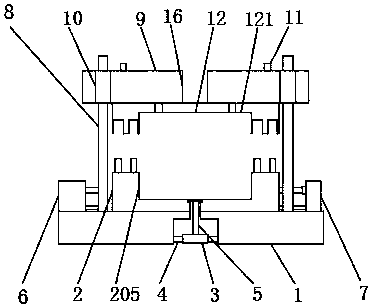
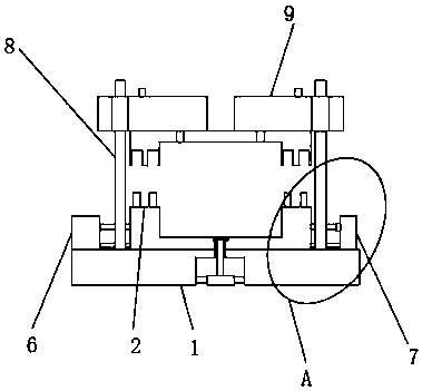
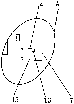
[0039] see Figure 1-10 , the present invention provides a technical solution: a high-efficiency cooling plastic mold, including a lower template 1, the user installs the upper template 9 and the lower template 1 together, and the guide post 8 on the lower template 1 will pass through the upper template 9 to avoid the dislocation of the connection between the lower mold body 2 and the upper mold body 12, and avoid the deformation of the molding m...


PUM


Abstract

The invention discloses an efficient cooling type plastic mold. The efficient cooling type plastic mold comprises a lower mold plate, wherein a lower mold body is fixedly installed on the outer surface of the upper end of the lower mold plate, a lower mold cavity is formed in the inner surface of the lower mold body, and a jacking motor is arranged in the middle of the interior of the lower mold plate; fixing bases are welded to the outer surfaces of the two sides of the jacking motor, and the jacking motor is fixedly connected to the lower mold plate through the fixing bases; and an ejectioncolumn penetrates through the interior of the lower mold plate, a cooling box is fixedly arranged at the position, close to one side, of the outer surface of the upper end of the lower mold plate, anda water delivery tank is welded to the position, close to the other side, of the outer surface of the upper end of the lower mold plate. According to the efficient cooling type plastic mold, the injected raw materials can be better and rapidly cooled, and the friction among mold parts is reduced, the service life of the mold is prolonged, moreover, the formed raw materials can be better ejected out, and the situation that the formed raw materials are damaged in the ejection process is effectively avoided.

Description

technical field [0001] The invention relates to the field of molds, in particular to an efficient cooling plastic mold. Background technique [0002] Plastic mold is the abbreviation of a combined mold used for compression molding, extrusion molding, injection molding, blow molding and low foaming molding. The coordinated change of mold convex, concave mold and auxiliary molding system can process different shapes and sizes. A series of plastic parts, the plastic mold mainly includes a concave mold with a variable cavity composed of a die combination base plate, a die assembly and a die combination clamping plate, and a punch combination base plate, a punch assembly, and a punch combination Punches with variable cores composed of pallets, cavity cut-off components, and side-cut composite plates, etc., the cooling effect of the existing plastic molds is not good enough, so that the cooling of the raw materials injected into the mold is slow, which cannot meet the needs of use...

Claims


Application Information

Patent Timeline
IPC IPC(8): B29C45/26B29C45/73B29C45/40
CPCB29C45/26B29C45/2606B29C45/4005B29C45/7312
Inventor 陈婷
Owner 东莞市竣詹机械科技有限公司
Learn More