Two-wheel self-balancing trolley
A self-balancing car and two-wheel technology, applied in the field of balancing cars, can solve the problems of controller and actuator driving error, interference, and vulnerability to impact, and achieve reliable control and precise operation control.
- Summary
- Abstract
- Description
- Claims
- Application Information
AI Technical Summary
Problems solved by technology
Method used
Image
Examples
Embodiment 1
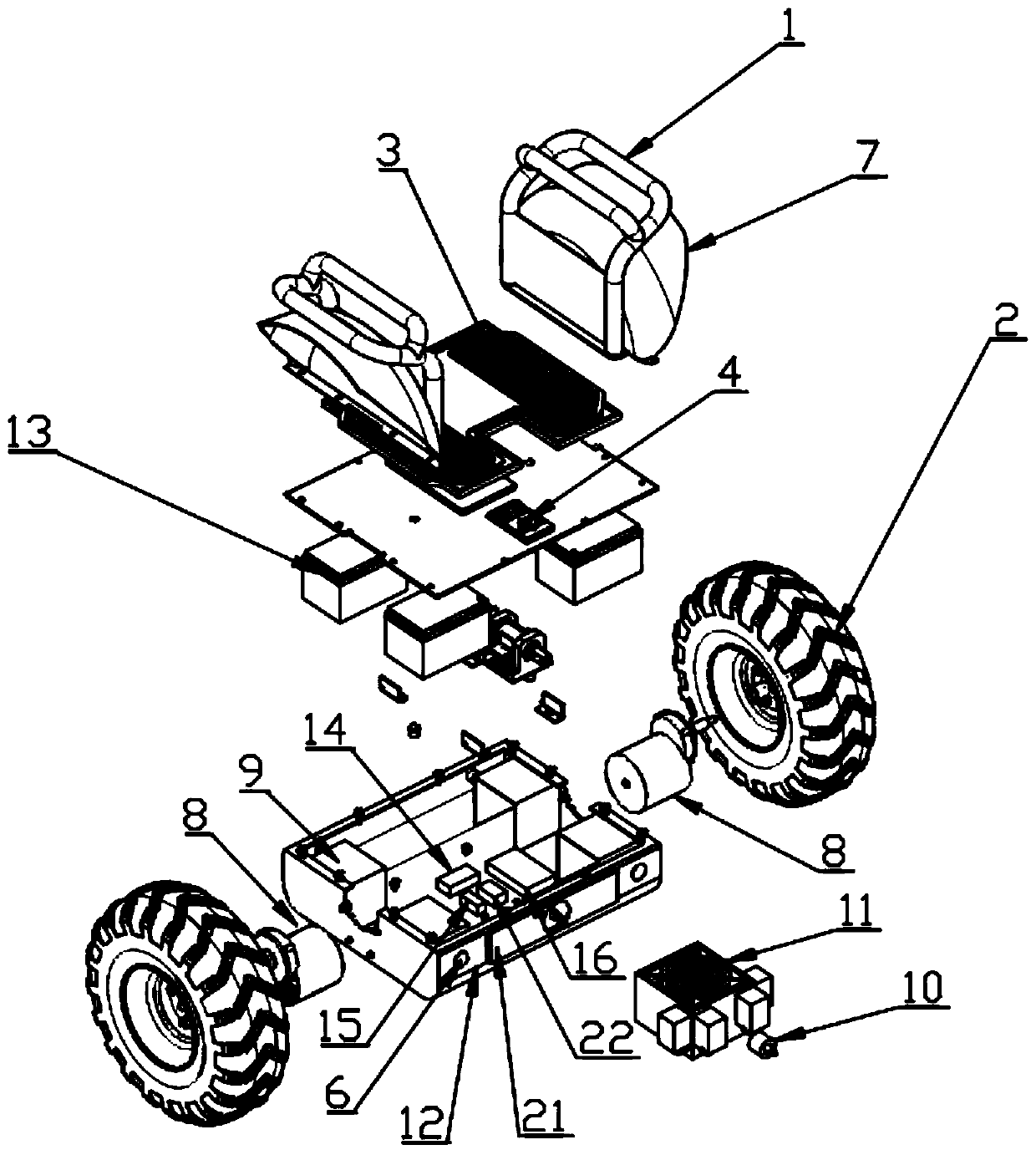
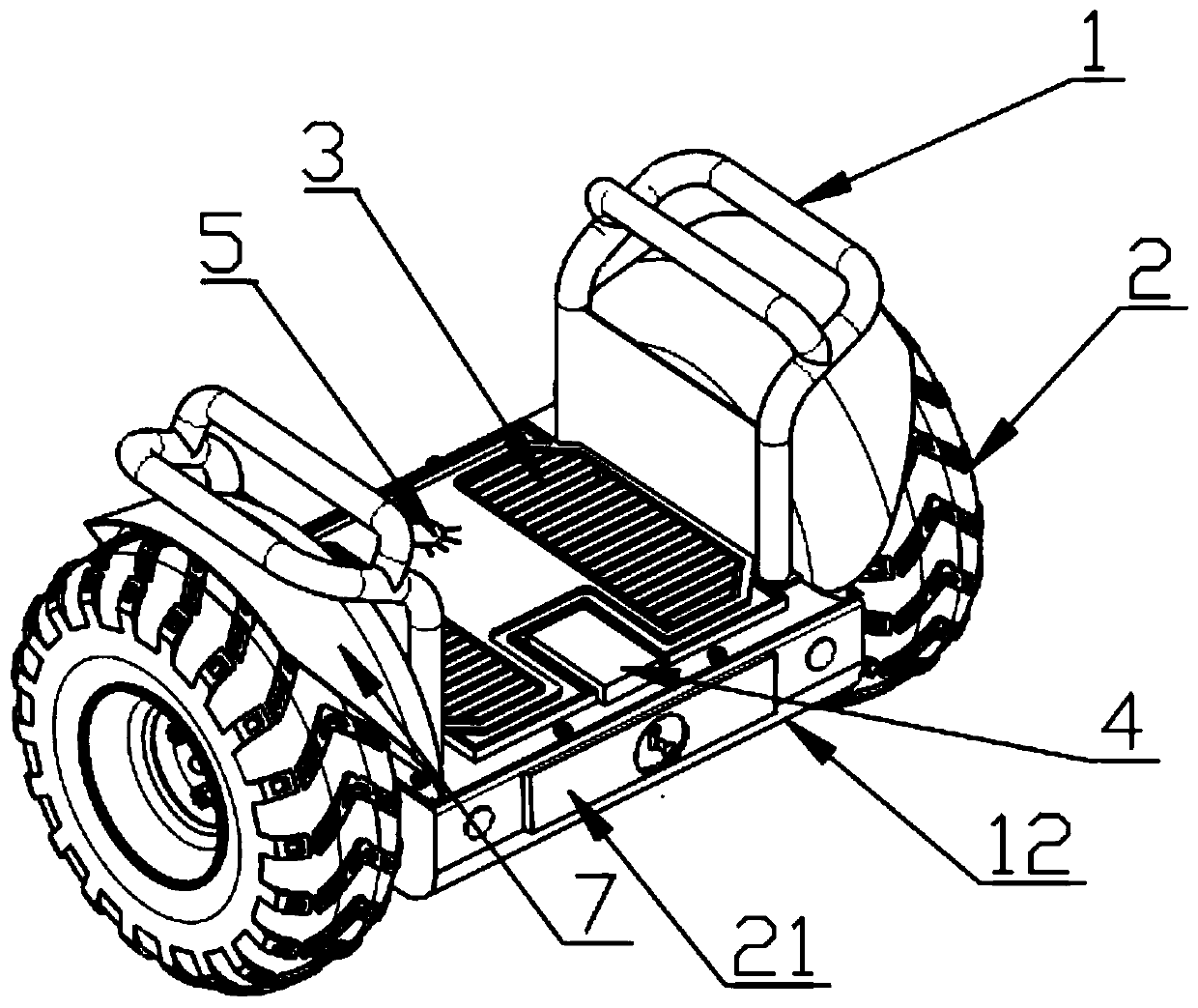
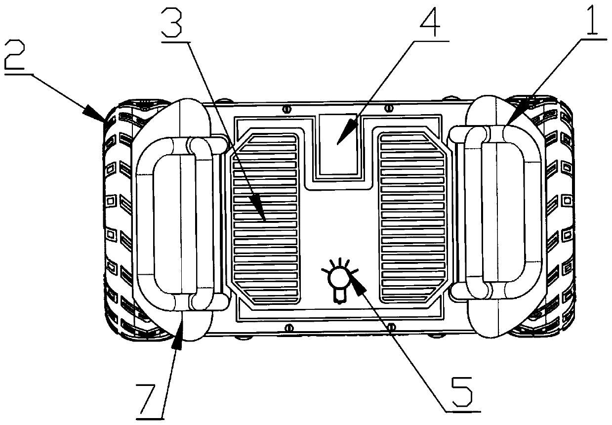
[0025] Embodiment one: if Figure 1-5 As shown, a two-wheel self-balancing vehicle includes a frame 12, wheels 2, power storage device 13, pedal device 3, drive mechanism 8, six-axis inertial sensor 11, steering trigger device, wireless communication module 15 and controller 14 , the wheels 2 are movably connected with the drive mechanism 8 and arranged on both sides of the vehicle frame 12, the power storage device 13 is fixedly installed on the bottom plate of the frame 12, and the pedal device 3 is arranged on On the top surface of the vehicle frame 12, the controller 14 is fixedly connected to the vehicle frame 12 and arranged inside the vehicle frame 12, the wireless communication module 15 includes a receiving end and a transmitting end, the control One side of the controller 14 is provided with the six-axis inertial sensor 11, and the other side of the controller 14 is provided with the receiving end 15 of the wireless communication module, and the transmitting end 20 o...
Embodiment 2
[0032] Embodiment two: on the basis of embodiment one, adopt correction algorithm to optimize in the present embodiment, concrete expression is as follows:
[0033] PWM=angle·Kp+Gyro_y·Kd+V·Kps+Vi·Kis+Gyro_z·Kpt
[0034] in:
[0035] angle: balance angle deviation (inclination)
[0036] Gyro_y: y-axis angular velocity
[0037] V: speed deviation
[0038] Vi: speed deviation integral
[0039] Gyro_z: z-axis angular velocity
[0040] The block diagram of the correction algorithm is as follows Figure 5 shown. The tuning steps of the correction algorithm are as follows: (1) Only the proportional control link is added to the control system, and other parameters are set to zero, and the parameter Z is increased until the system has a critical oscillation, and finally Z is determined to be 60%-70% of the current value; (2) After the parameter Z is determined, take a larger Ti value randomly, then gradually reduce Ti until the system oscillates, and then in turn, gradually inc...
Embodiment 3
[0041] Embodiment 3: On the basis of Embodiment 1 and Embodiment 2, a collision avoidance device 22 is provided in the frame of this embodiment, and the collision avoidance device 22 includes a ranging sensor 10, and the collision avoidance device 22 It is connected with the controller 14 and can perform data transmission with the controller 14 . The middle part of the front guard plate of the frame 12 is provided with a circular through hole, and the distance measuring sensor 10 is provided directly opposite the through hole. The distance measuring sensor 10 includes but not limited to the following examples: ultrasonic distance measuring sensor, infrared ranging sensor, laser ranging sensor. The collision avoidance device 22 is preset with a safety distance value, a braking distance value and an emergency braking distance value. When the distance between the balance car and the obstacle is from far to near, the distance measuring sensor 10 will transmit the signal to the co...
PUM
 Abstract
Description
Claims
Application Information
 - R&D
- Intellectual Property
- Life Sciences
- Materials
- Tech Scout
- Unparalleled Data Quality
- Higher Quality Content
- 60% Fewer Hallucinations
Browse by: Latest US Patents, China's latest patents, Technical Efficacy Thesaurus, Application Domain, Technology Topic, Popular Technical Reports.
© 2025 PatSnap. All rights reserved.Legal|Privacy policy|Modern Slavery Act Transparency Statement|Sitemap|About US| Contact US: help@patsnap.com


