

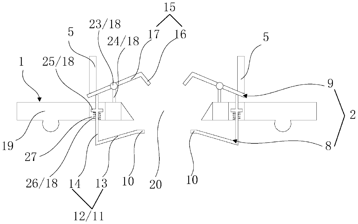
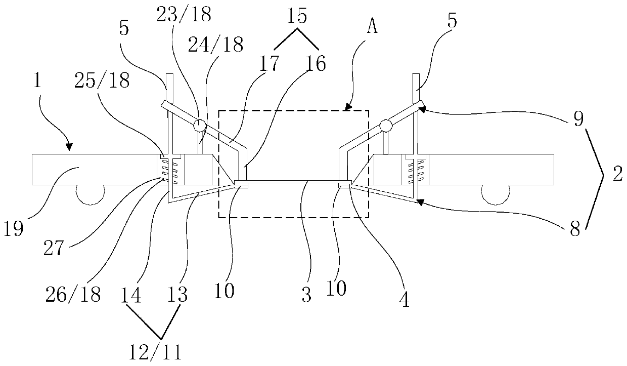
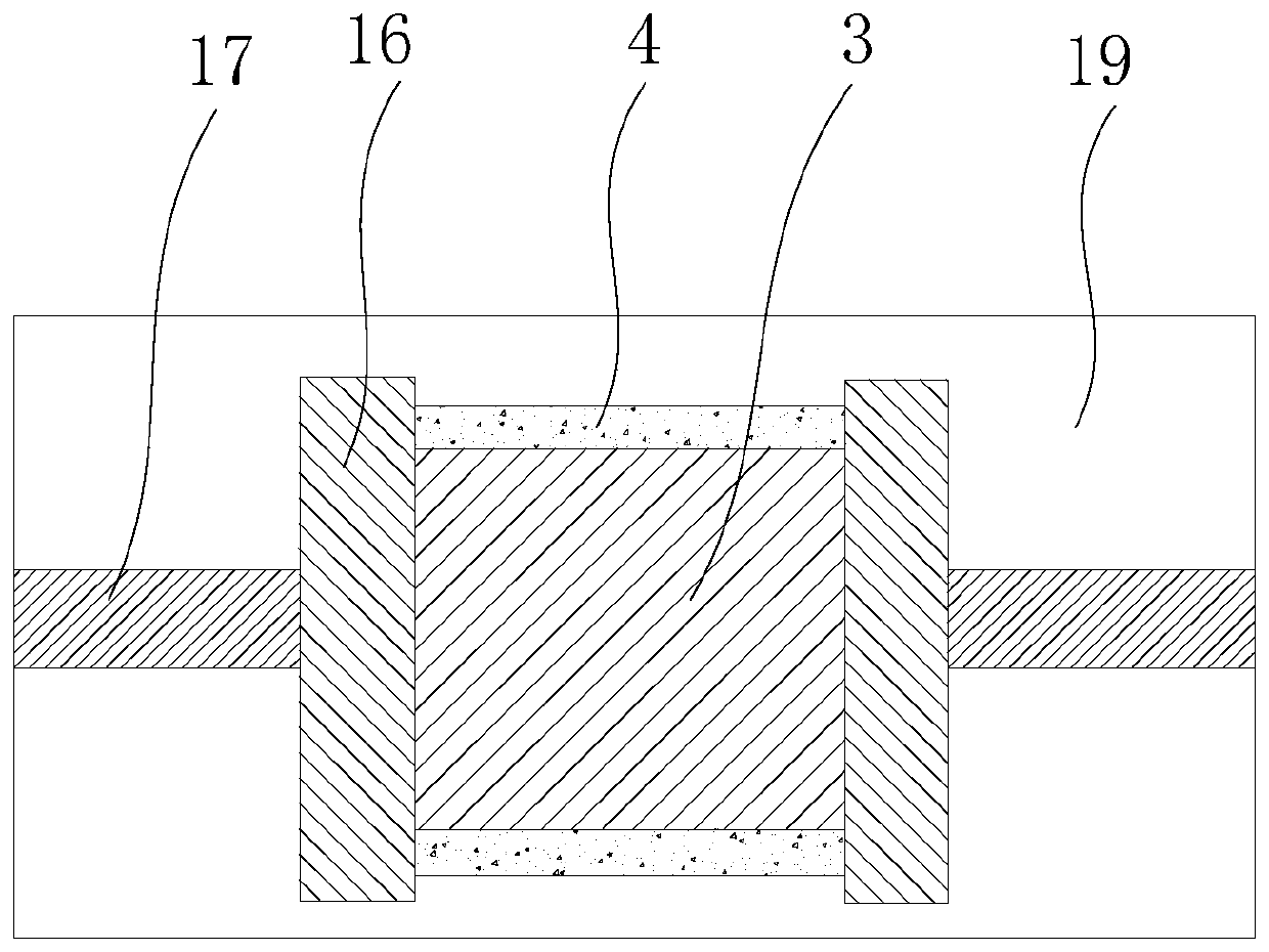
Clamping device applied to sputtering coating equipment, and sputtering coating equipment
A clamping device and sputtering technology, which is applied in the field of sputtering coating equipment, can solve the problems of substrate film formation shadows, film layer falling off and polluting the sputtering chamber, mask plate warping and deformation, etc., so as to avoid film formation shadows , avoid the effect of loose fit and warping deformation
- Summary
- Abstract
- Description
- Claims
- Application Information
AI Technical Summary
Problems solved by technology
Method used
Image

Examples
Embodiment Construction
[0030] Specific structural and functional details disclosed herein are representative only and are for purposes of describing example embodiments of the present application. This application may, however, be embodied in many alternative forms and should not be construed as limited to only the embodiments set forth herein.
[0031] In the description of this application, it should be understood that the terms "central", "lateral", "upper", "lower", "left", "right", "vertical", "horizontal", "top", The orientation or positional relationship indicated by "bottom", "inner", "outer", etc. is based on the orientation or positional relationship shown in the drawings, and is only for the convenience of describing the application and simplifying the description, rather than indicating or implying the referred device Or elements must have a certain orientation, be constructed and operate in a certain orientation, and thus should not be construed as limiting the application. In addition...
PUM
 Abstract
Description
Claims
Application Information