Block Compressed Sensing Method Based on Adaptive Sampling and Smooth Projection
A block-based compressed sensing and adaptive sampling technology, applied in image analysis, image enhancement, instrumentation, etc., can solve the problems of high algorithm complexity and low reconstructed image quality, and achieve reduced algorithm complexity and fast reconstruction speed. , the effect of improving quality
- Summary
- Abstract
- Description
- Claims
- Application Information
AI Technical Summary
Problems solved by technology
Method used
Image
Examples
specific Embodiment approach 1
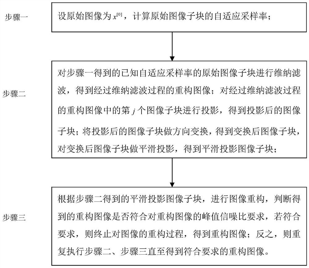
[0036] Specific implementation mode 1: The implementation mode of the present invention is based on the adaptive sampling and smooth projection block compression sensing method. The specific process is as follows:
[0037] Basic theory of compressed sensing
[0038] From the perspective of compressed sensing, to recover from M observations And M Φ is an M×N observation matrix, and its sampling rate is R=M / N. The CS theory points out that if x is sufficiently sparse under a certain transformation basis ψ, x can be recovered from y according to the following optimization method.
[0039]
[0040] As long as Φ and ψ are sufficiently uncorrelated, M is large enough. For high-dimensional signals such as image signals, when the sampling operator Φ is stored as a dense matrix, a large amount of storage space will be required. In addition, high dimensionality can make the reconstruction process time-consuming [13] . Therefore, for image sampling and reconstruction, more effic...
specific Embodiment approach 2
[0045] Specific embodiment 2: The difference between this embodiment and specific embodiment 1 is that in the step 1, the original image is set as x [0] , to calculate the adaptive sampling rate of the original image sub-block; the specific process is:
[0046] Calculation of Adaptive Sampling Rate
[0047] Using block-based compressed sensing algorithm (Block-based CS, BCS), the target image signal is first transformed into wavelet domain, and then divided into blocks of the same size but not overlapping. The size of each image block is B×B, using the same observation matrix Φ B Each image sub-block is observed separately. assuming x i is the original input image of the i-th block, then its output block can be expressed as
[0048] the y i = Φ B x i
[0049] In the formula, Φ B is the matrix for M B ×B 2 The observation matrix of Φ B Not associated with image blocks. x i is with B 2 A column vector of samples. In BCS, the entire measurement matrix Φ becomes a ...
specific Embodiment approach 3
[0061] Specific embodiment three: the difference between this embodiment and specific embodiment one or two is that the ith high-frequency sub-band (Y) is calculated in the step one or three (i) energy E i ; The specific process is:
[0062] i-th high-frequency sub-band (Y) (i) energy E i The expression is:
[0063]
[0064] In the formula, c(m,n) represents the i-th high-frequency subband (Y) (i) The coefficient at the (m,n) position in the middle; P and Q respectively represent the i-th high-frequency subband (Y) (i) Rows and columns; (m,n) represents the i-th high-frequency subband (Y) (i) location point.
[0065] Other steps and parameters are the same as those in Embodiment 1 or Embodiment 2.
PUM
 Abstract
Description
Claims
Application Information
 - R&D
- Intellectual Property
- Life Sciences
- Materials
- Tech Scout
- Unparalleled Data Quality
- Higher Quality Content
- 60% Fewer Hallucinations
Browse by: Latest US Patents, China's latest patents, Technical Efficacy Thesaurus, Application Domain, Technology Topic, Popular Technical Reports.
© 2025 PatSnap. All rights reserved.Legal|Privacy policy|Modern Slavery Act Transparency Statement|Sitemap|About US| Contact US: help@patsnap.com


