
Display apparatus

A technology for display equipment and display panels, applied in branch equipment, computer monitor casings, casings with display/control units, etc.

Active Publication Date: 2019-08-27
LG ELECTRONICS INC
View PDF6 Cites 3 Cited by
  • Summary
  • Abstract
  • Description
  • Claims
  • Application Information

AI Technical Summary

Problems solved by technology

However, the output amplitude in the low frequency range of the piezoelectric vibration device is smaller than that of the moving coil device

Method used


Image

  • Display apparatus
  • Display apparatus
  • Display apparatus

Examples


Embodiment Construction

[0085] Reference will now be made in detail to the preferred embodiments of the invention, examples of which are illustrated in the accompanying drawings. Wherever possible, the same reference numbers will be used throughout the drawings to refer to the same or like parts.

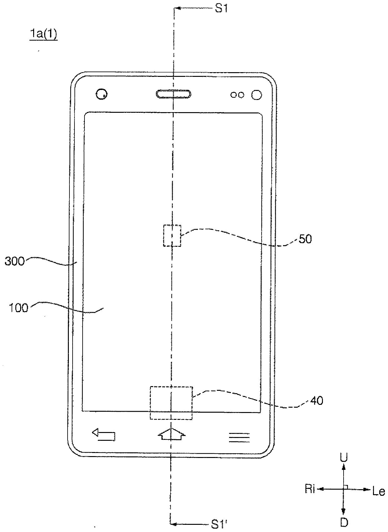
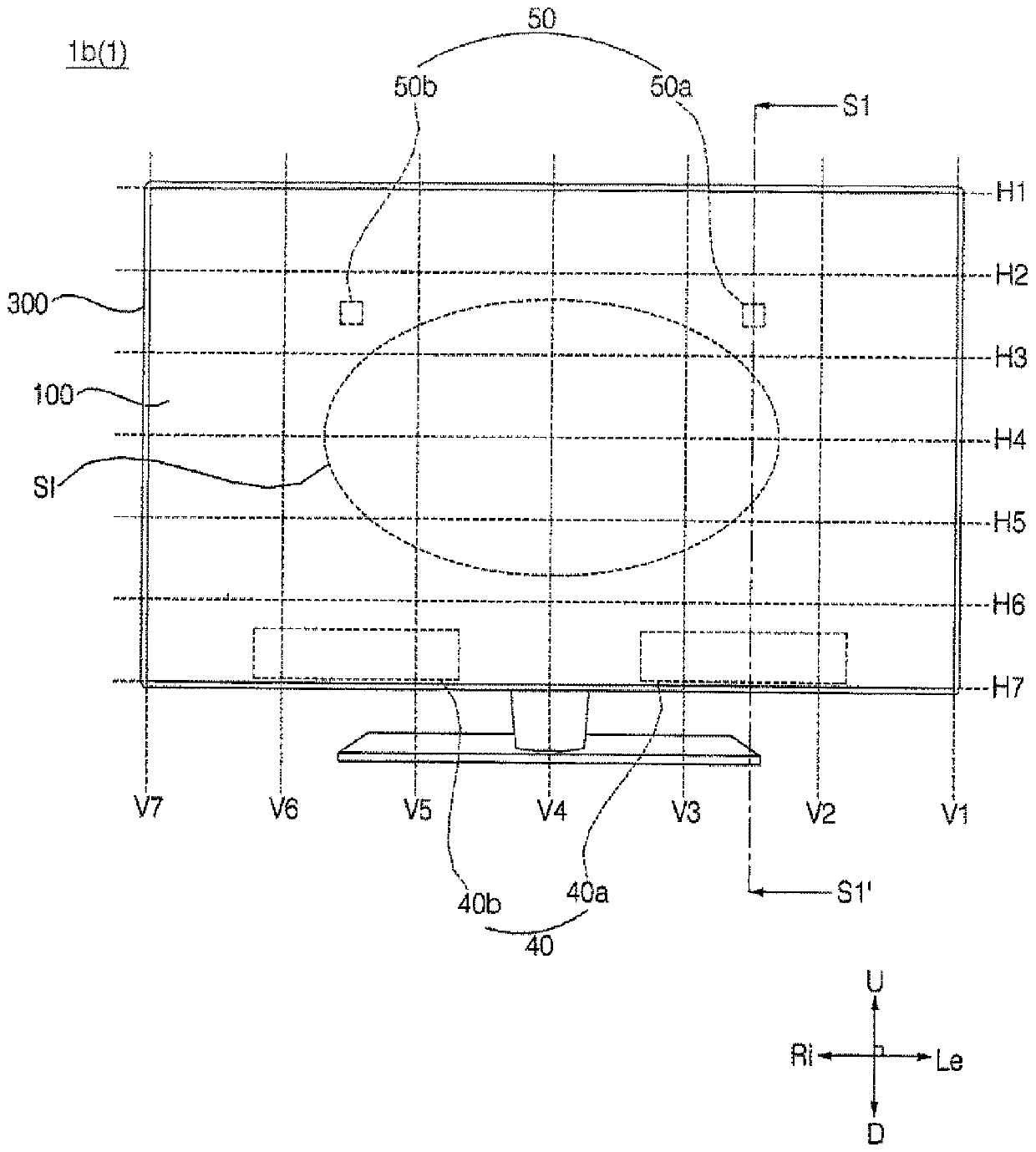
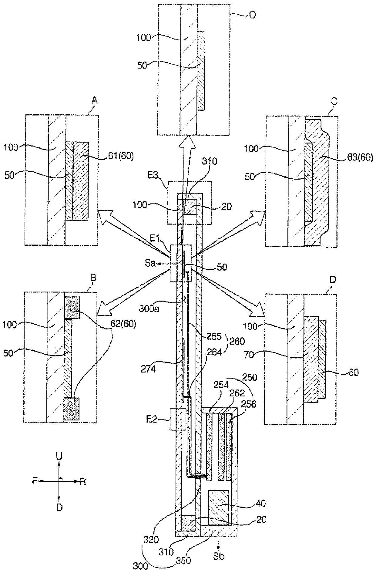
[0086] Terms indicating directions such as "front (F)", "rear (R)", "left (Le)", "right (Ri)", "upper (U)" and "lower (D)" are hereinafter referred to as mentioned, will be based on Figure 1 to Figure 8 to understand. Specifically, the terms 'front' and 'rear' are defined such that the direction in which the display panel 100 outputs an image is defined as the front. According to this definition, in the case where the display panel 100 is implemented as a flat display panel like an embodiment of the present invention, the front and rear are the same over the entire area of ​​the display panel 100, but where the display panel 100 is implemented as a curved In the case of the display panel, the front and...


PUM


Abstract

A display apparatus is disclosed. The display apparatus includes a display panel, a piezoelectric vibration unit attached to a rear surface of the display panel, and a member attached to at least oneof a rear surface of the piezoelectric vibration unit and a portion of the rear surface of the display panel that surrounds the piezoelectric vibration unit. The display apparatus includes a display panel, a damping member attached to a rear surface of the display panel, and a piezoelectric vibration unit attached to a rear surface of the damping member.

Description

technical field [0001] The present invention relates to a display device that generates vibrations. Background technique [0002] There are various display panels for generating images, for example, liquid crystal display (LCD), plasma display panel (PDP), electroluminescent display (ELD), vacuum fluorescent display (VFD), organic light emitting diode (OLED) display, etc. . [0003] A display device has been developed that is equipped with a display panel and a vibration unit for generating vibration. The vibration unit refers to an acoustic output device (eg, a speaker) or a tactile device (eg, a linear motor) that enables a user to feel a tactile vibration. [0004] Representative examples of the vibration unit include a dynamic device (for example, a dynamic speaker) that generates vibration energy by applying an electric current to a coil, and a piezoelectric vibration device (for example, a piezoelectric actuator) that generates vibration using a piezoelectric effect....

Claims


Application Information

Patent Timeline
Patent Type & Authority Applications(China)
IPC IPC(8): H04R1/02H04R7/04H04R17/00G06F3/01H04M1/03
CPCB06B1/06G06F1/1605G06F1/1626G06F1/1637G06F1/1684G06F1/1688H04R17/00H04R1/26H04R2499/11H04R2499/15G06F3/016G06F3/01H04M1/0266H04M1/03H04R7/045H04R2400/03H04R2440/05H10N30/88H04R1/025H04R7/04H05K5/0017H05K5/03H10N30/20H10N30/883H10N30/8554
Inventor 朴钟河
Owner LG ELECTRONICS INC
Learn More