
Counter-rotating bladeless stirring device and method

A stirring device and counter-rotating technology, applied in chemical instruments and methods, transportation and packaging, dissolving and other directions, can solve the problems such as the inability to achieve continuous and stable operation of the device, the complex structure of the mechanical stirring device, and the easy damage to the seal and other structures. Simple structure, low cost, convenient installation and maintenance

Active Publication Date: 2019-08-30
CHINA UNIV OF MINING & TECH
View PDF10 Cites 4 Cited by
  • Summary
  • Abstract
  • Description
  • Claims
  • Application Information

AI Technical Summary

Problems solved by technology

The traditional effective stirring method is mechanical stirring, but the structure of the mechanical stirring device is relatively complicated, the installation is difficult, and it is easy to wear and corrode
Due to the existence of wearing parts such as rotating mechanisms in mechanical stirring, structures such as seals are easily damaged during operation, and regular shutdowns are required for maintenance and replacement, which cannot achieve continuous and stable operation of the device, resulting in high maintenance and operation costs

Method used


Image

  • Counter-rotating bladeless stirring device and method
  • Counter-rotating bladeless stirring device and method
  • Counter-rotating bladeless stirring device and method

Examples


Embodiment Construction

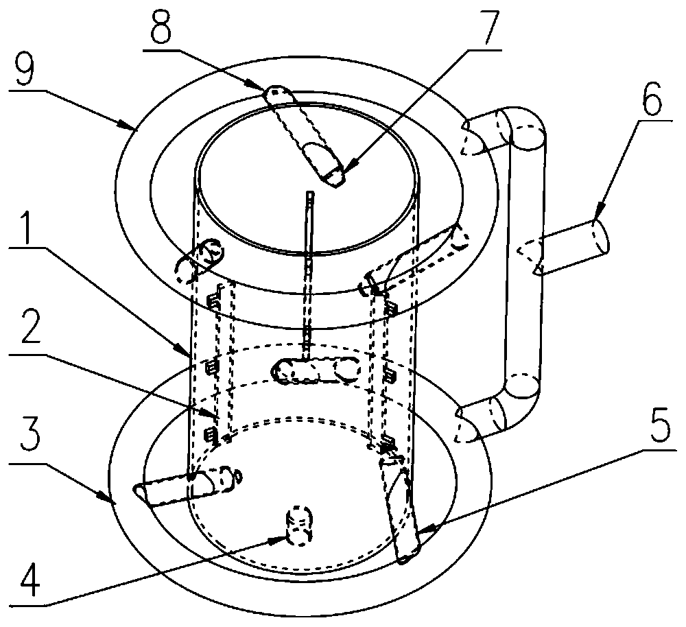
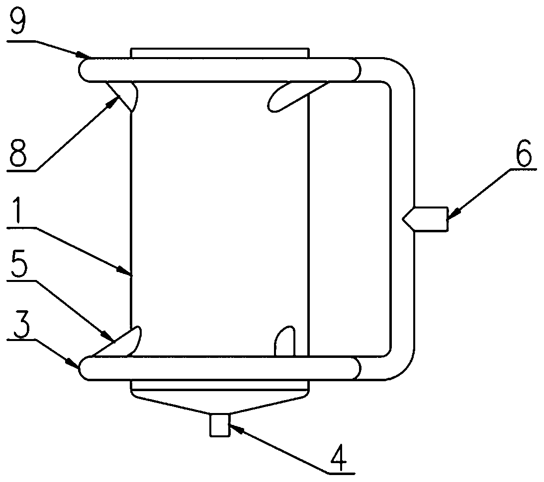
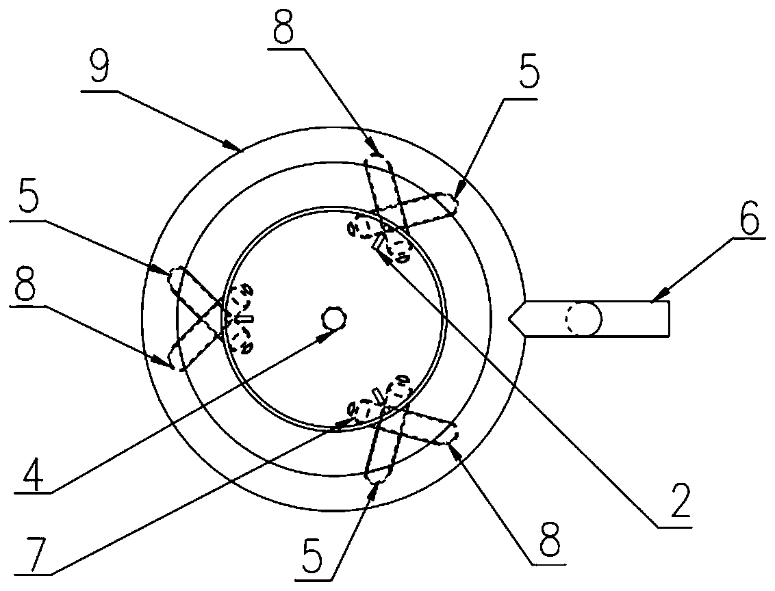
[0023] The present invention will be further described below in conjunction with accompanying drawing.

[0024] Such as figure 1 , figure 2 and image 3 As shown, the counter-rotating bladeless stirring device of the present invention is characterized in that: it includes a columnar structure cylinder 1 and a stirring mixing device, the cylinder 1 is provided with a discharge port 4 of a funnel structure, and the cylinder 1 inner wall surface There are three vertically arranged baffles 2 evenly distributed, and the top of the cylinder body 1 is respectively provided with a feeding port 10 and a chemical feeding port 11. The whole device is completely closed and does not allow the slurry to splash outward;

[0025] The stirring and mixing device includes a lower distribution ring 3 and an upper distribution ring 9 arranged around the outside of the cylinder body 1, the lower distribution ring 3 is arranged on the periphery below the cylinder body 1, and the upper distributio...


PUM


Abstract

The invention relates to a counter-rotating bladeless stirring device and a method, which are suitable for use in the field of coal chemical industry. The counter-rotating bladeless stirring device includes a cylinder body of a columnar structure and a stirring and mixing device, wherein a discharge port of a funnel structure is arranged below the cylinder body, three vertical baffles are evenly distributed on the inner wall surface of the cylinder body, and the top of the cylinder body is provided with a feeding port and a dosing port; the mixing and stirring device includes a lower distribution ring and an upper distribution ring arranged outside the cylinder body in a surrounding mode, wherein the lower distribution ring and the upper distribution ring are connected through a tee jointwhere a feed port is provided, the feed port and the discharge port are connected to each other by a pipe, and the pipe is provided with a pump for pressurization; the discharge port is further provided with a taking port, a plurality of lower feed pipes are arranged between the lower distribution ring and the cylinder body, and a plurality of upper feed pipes are arranged between the upper distribution ring and the cylinder body. The counter-rotating bladeless stirring device has the advantages of simple structure, convenient use, convenient installation and maintenance, low cost and good stirring effect, and has no need of a stirring device, since stirring and mixing can be realized by just using pressurized slurry per self to agitate and disturb the flow field.

Description

technical field [0001] The invention relates to a stirring device and method, in particular to a counter-rotating bladeless stirring device and method used in the field of coal chemical industry. Background technique [0002] Stirring device is a necessary equipment in the pulp treatment process, and the stirring effect has an important influence on the flotation of pulp. The traditional effective stirring method is mechanical stirring, but the structure of the mechanical stirring device is relatively complicated, the installation is difficult, and it is easy to wear and corrode. Due to the existence of wearing parts such as rotating mechanisms in mechanical stirring, structures such as seals are easily damaged during operation, and need to be stopped for maintenance and replacement on a regular basis. The continuous and stable operation of the device cannot be achieved, resulting in high maintenance and operation costs. Contents of the invention [0003] Technical proble...

Claims


Application Information

Patent Timeline
Patent Type & Authority Applications(China)
IPC IPC(8): B01F5/10B01F5/00
CPCB01F2025/913B01F2025/918B01F25/51B01F2101/50
Inventor 闫小康王利军张海军粟文兵杨涵曦李晓恒苏子旭李娟
Owner CHINA UNIV OF MINING & TECH
Learn More