Gear manufacturing method and manufacturing device
A technology of manufacturing device and manufacturing method, which is applied in the field of gear manufacturing and manufacturing device, and can solve problems such as density reduction and internal cracking of teeth.
- Summary
- Abstract
- Description
- Claims
- Application Information
AI Technical Summary
Problems solved by technology
Method used
Image
Examples
Embodiment approach 1
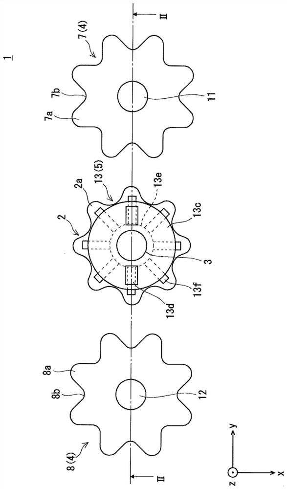
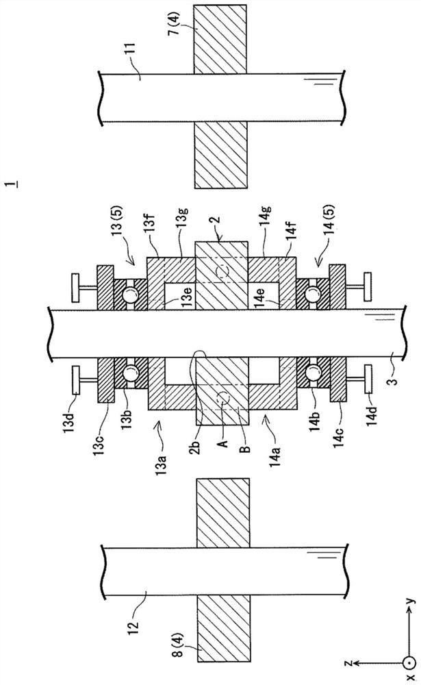
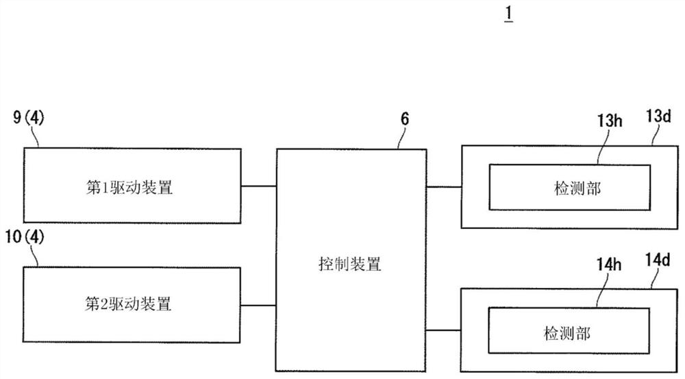
[0042] First, the structure of the manufacturing apparatus of the gear of this embodiment is briefly demonstrated. figure 1 It is a plan view which schematically shows the manufacturing apparatus of the gear of this embodiment. figure 2 is along figure 1 A partial cross-sectional view cut along the line II-II. image 3 It is a block diagram showing the control system of the manufacturing apparatus of the gear of this embodiment. In addition, in the following description, for clarity of description, a three-dimensional (XYZ) coordinate system is used for description. In addition, in the following description, it demonstrates on the premise that the rolling gear blank is arrange|positioned in the manufacturing apparatus of a gear.
[0043] Such as figure 1 as well as figure 2 As shown, the gear manufacturing device (hereinafter, sometimes simply referred to as the manufacturing device) 1 of this embodiment is preferably used when manufacturing a gear by rolling the too...
Embodiment approach 2
[0084] The protrusions 13g and 14g in Embodiment 1 are rectangular when viewed from the Z-axis direction, but they may be as follows: Figure 9 As shown, it has a substantially circular shape when viewed from the Z-axis direction. However, the protruding portions 13g and 14g should be able to cover at least the area A in the tooth portion 2a of the gear blank 2 at a predetermined depth including at least the region A where the density inside the tooth portion 2a is reduced. The shape of area B to be extruded is sufficient. here, in Figure 9 In , one protrusion is shown as an example.
Embodiment approach 3
[0086] In Embodiment 1, in the tooth portion 2a of the gear blank 2, the area B including at least the area A in which the density inside the tooth portion 2a is reduced when the rolling process is performed is pressed, but the present invention is not limited to here. Figure 10 It is a plan view which schematically shows the manufacturing apparatus of the gear of this embodiment. Figure 11 is along Figure 10 Partial cross-sectional view of XI-XI line section. In addition, since the manufacturing method and manufacturing apparatus of the gear of this embodiment are substantially the same as the manufacturing method and manufacturing apparatus of the gear of Embodiment 1, repeated description is abbreviate|omitted, and the same code|symbol is used for the same member.
[0087] The manufacturing apparatus 21 of this embodiment is provided with the press plates 22 and 23 instead of the punch part 13a and the punch part 14a of Embodiment 1. As shown in FIG. That is, the manu...
PUM
 Abstract
Description
Claims
Application Information
 - R&D
- Intellectual Property
- Life Sciences
- Materials
- Tech Scout
- Unparalleled Data Quality
- Higher Quality Content
- 60% Fewer Hallucinations
Browse by: Latest US Patents, China's latest patents, Technical Efficacy Thesaurus, Application Domain, Technology Topic, Popular Technical Reports.
© 2025 PatSnap. All rights reserved.Legal|Privacy policy|Modern Slavery Act Transparency Statement|Sitemap|About US| Contact US: help@patsnap.com


