Automatic control system for cross-cut shear blade gap

A technology of automatic control and cutting edge clearance, applied in the field of cross-cutting shears, can solve the problems of large amount of equipment modification, abnormal collapse of cross-cutting shears, and difference in cutting quality, so as to reduce deviation and improve The effect of cut surface quality

Active Publication Date: 2019-08-30
BAOSHAN IRON & STEEL CO LTD
View PDF6 Cites 2 Cited by
  • Summary
  • Abstract
  • Description
  • Claims
  • Application Information

AI Technical Summary

Problems solved by technology

However, in actual daily use, there are two typical abnormalities as follows: (1) The gap between the cutting blades of the cross-cutting shears is set according to the percentage of the thickness of the steel plate (usually 10% of the thickness of the plate) according to the design of the equipment manufacturer. This setting method is not scientific and reasonable enough
It shows that the shear quality of steel plates with the same thickness and specifications and different steel types is greatly different; when steel plates with the same thickness and specifications and steel types are sheared at different times, the shear quality is different
(2) if figure 1 , figure 2 As shown, the cross-cut shears have 4 pairs of wedges for gap adjustment in the full length direction of the cutting edge. There is a deviation in the cutting surface, which is manifested by the difference in the shearing quality at different positions of the same cutting surface; there is abnormal chipping in the cutting edge of the cross-cutting shear, etc.
As described in the patent, the combination of front and rear wedges is used to adjust the gap, the amount of equipment changes is huge, and there are great limitations in its technical promotion.

Method used


Image

  • Automatic control system for cross-cut shear blade gap
  • Automatic control system for cross-cut shear blade gap
  • Automatic control system for cross-cut shear blade gap

Examples


Embodiment Construction

[0027] The technical solutions of the present invention will be further described below in conjunction with the accompanying drawings and embodiments.

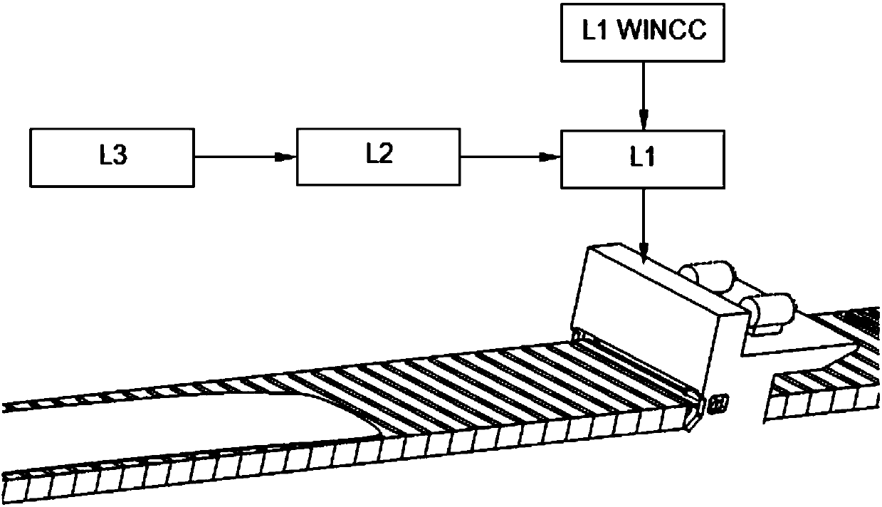
[0028] refer to image 3 As shown, in order to solve the problem of unreasonable setting of the gap between the cutting blades of the cross-cutting shears, the automatic control system for the gaps between the cutting blades of the cross-cutting shears of the present invention mainly includes: a production control computer L3, a process automation computer L2 and a basic automation computer L1, wherein:

[0029] The production control computer L3 sends the original PDI data of the steel plate to be sheared (here mainly refers to the three-dimensional size, tensile strength, etc. of the steel plate) to the process automation computer L2;

[0030] The process automation computer L2 automatically calculates the optimal cutting edge gap value according to the received original data of the steel plate combined with the static param...


PUM

PropertyMeasurementUnit
lengthaaaaaaaaaa

Abstract

The invention discloses an automatic control system for a cross-cut shear blade gap. A process automation computer calculates an optimal shear blade gap value by comprehensively considering the thickness and the tensile strength of a steel plate according to original data of the steel plate to be sheared sent by a production control computer, the optimal shear blade gap value is automatically sentto a base automation computer, and the base automation computer further considers a shear blade actual wear compensation dosage and then automatically sends a final optimal shear blade gap value to ashearing machine automation control programmable logic controller (PLC) for carrying out shearing. The automatic control system for the cross-cut shear blade gap has the advantages that the shear blade gap is scientific, reasonable and targeted, so that the quality of cut surfaces of various steel plates especially high-strength steel is effectively improved. In addition, a gasket for clearance adjustment is further cushioned on a top knife rest, so that the deviation of the gap in the shear blade length direction is reduced, a method is simple and easy to implement, and the remarkable effects on improving the overall quality of the cut surface and prolonging the service life of the shear blade are achieved.

Description

technical field [0001] The present invention relates to the cutting edge of cross-cutting shears, and more specifically relates to an automatic control system for the gap between cutting blades of cross-cutting shears. Background technique [0002] The thick plate shearing line is usually equipped with two cross-cutting shears, namely the head shear and the cut-to-length shear, which are respectively used for cutting the head and tail of the rolled large plate, segmenting and cutting the finished product to length. [0003] Such as Figure 1 ~ Figure 2 As shown, the transverse shear adjusts its horizontal gap a through the wedge mechanism. According to the set value of the gap, the AC motor 1.2 drives the transmission shaft 1.3 to rotate through the gear box, and then the wedge lift control mechanism 1.1 controls the lift wedge 1.6 to drive the lift wedge 1.8 to lift. Under the interaction of the side spring 1.7, the movable knife rest 1.5 of the upper shear blade moves hor...

Claims


Application Information

Patent Timeline
Patent Type & Authority Applications(China)
IPC IPC(8): B23D35/00B23D33/00B23Q15/12
CPCB23D33/00B23D35/00B23Q15/12
Inventor 朱剑恩丁海绍
Owner BAOSHAN IRON & STEEL CO LTD
Why Eureka
Try Eureka