Gripper with guided cleaning function

A gripper and functional technology, applied in the field of grippers with guided cleaning function, can solve the problems affecting the processing quality of workpieces, the wear of the clamping block clamping structure, etc.

Active Publication Date: 2019-08-30
CHONGQING HONGGANG CNC MACHINE TOOL
View PDF7 Cites 1 Cited by
  • Summary
  • Abstract
  • Description
  • Claims
  • Application Information

AI Technical Summary

Problems solved by technology

[0003] The present invention intends to provide a clamper with a guide cleaning function, so as to improve the problem that the clamping block

Method used


Image

  • Gripper with guided cleaning function
  • Gripper with guided cleaning function
  • Gripper with guided cleaning function

Examples


Embodiment 1

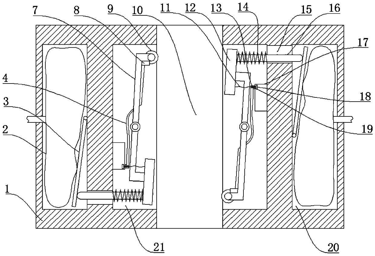
[0021] Embodiment 1, basically as attached figure 1 Shown: a holder with guided cleaning function, including a base 1, the base 1 is provided with an opening groove 10, and the base 1 on both sides of the opening groove 10 is provided with a clamping cavity 21, the clamping cavity 21 One side of the open groove 10 is open, and a lever 7 is arranged in the clamping cavity 21. One end of the lever 7 is welded with a clamping block 12, and the other end is equipped with a freely rotating guide wheel 9 through a pin shaft. The guide wheel 9 is hard. Rollers made of solid material. A tension spring 14 is bonded or welded between the clamping block 12 and the wall of the clamping chamber 21, and a drive chamber 20 is provided in the base 1 on the side of the clamping chamber 21 away from the opening groove 10, and a hydraulic drive chamber 20 is provided in the drive chamber 20. Mechanism, the hydraulic drive mechanism includes a hydraulic bladder 2, which communicates with the ext...

Embodiment 2

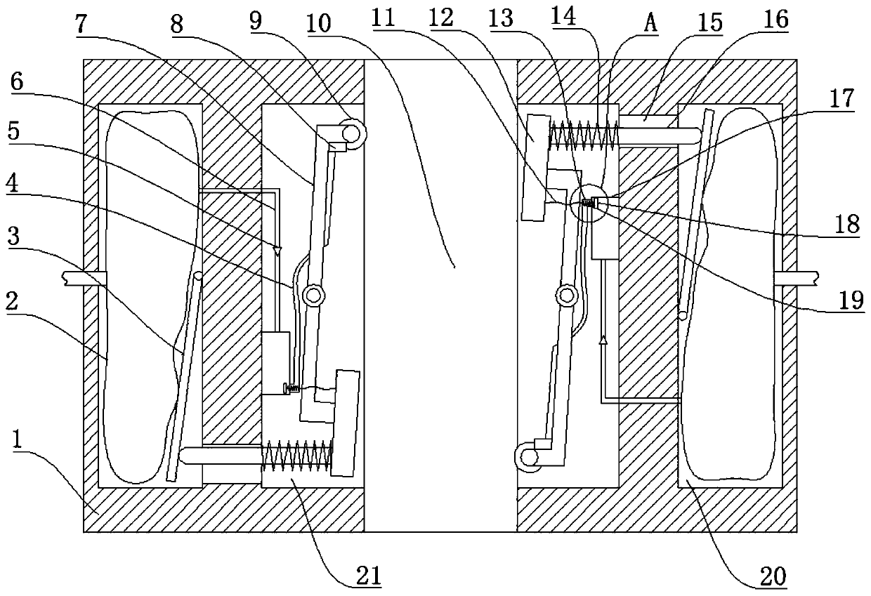
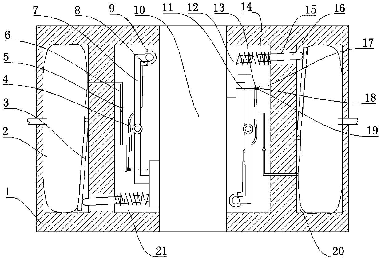
[0023] Example 2, combined with figure 2 , image 3 , Figure 4 As shown, this embodiment further improves the oil storage box 17 on the basis of Embodiment 1. Specifically, the oil storage box 17 is connected with an oil inlet pipe 6, and the oil inlet pipe 6 communicates with the hydraulic bag 2, and the oil inlet pipe 6 is The high-pressure pipe, the oil inlet pipe 6 is connected with a one-way valve 5 leading to the oil storage box 17 .

[0024]The specific implementation process is as follows: during use, the clamper of the present application is installed on the components of the CNC machine tool, and the clamper straddles the guide rail of the machine tool, that is, the guide rail passes through the open slot 10 of the clamper. During the movement of the component on the guide rail, the state of each component in the holder is as follows. The external hydraulic oil source does not provide hydraulic oil to the hydraulic bladder 2, and the oil pressure in the hydraulic...


PUM


Abstract

The invention discloses a gripper with a guided cleaning function and belongs to the field of machine tool grippers. The gripper comprises a substrate. An open slot is formed in the substrate in a penetrating manner, clamping cavities are formed in the positions, on two sides of the open slot, of the substrate, the clamping cavities are formed toward the opening of one side of the open slot, a lever is arranged in each clamping cavity, one end of each lever is connected to a clamping block while the other end of each lever is connected to a guide wheel, a tension spring is connected between each clamping block and the wall of the corresponding clamping cavity, a driving cavity is formed in the substrate of one side, deviated from the open lot, of each clamping cavity, a hydraulic driving mechanism is arranged in each driving cavity, and the output end of each hydraulic driving mechanism is rigidly connected to the corresponding clamping block. The gripper can effectively solve the problem that the processing quality of a workpiece is affected as a result of severe wear of a clamping structure of a clamping block of an existing numerically controlled machine tool for a long time.

Description

technical field [0001] The invention relates to the field of machine tool holders, in particular to a holder with guiding and cleaning functions. Background technique [0002] CNC machine tool is a kind of flexible and high-efficiency automatic machine tool, which represents the development direction of modern machine tool control technology. CNC machine tool includes multiple sliding components, such as tailstock, bed saddle, tool holder, etc. These components They are all slidably connected on the guide rail. While sliding, these components need to be precisely positioned to ensure accurate processing of the workpiece. In the prior art, a hydraulically driven gripper is installed between the above components and the guide rail. Press the holder tightly against the guide rail to complete the clamping. During the sliding process, the clamping block inevitably rubs against the surface of the guide rail. To ensure the smooth sliding process, lubricating oil is generally appli...

Claims


Application Information

Patent Timeline
IPC IPC(8): B23Q3/08B23Q11/00
CPCB23Q3/08B23Q3/082B23Q11/00
Inventor 汪传宏
Owner CHONGQING HONGGANG CNC MACHINE TOOL
Why Eureka
Try Eureka