Automatic milling machine feeding and charging device for and working method thereof

An automatic loading and unloading, milling machine technology, applied in the direction of metal processing, etc., can solve the problems of reducing production efficiency, easily causing danger, consuming a lot of physical strength and time, and achieve the effect of improving work efficiency and avoiding danger

Pending Publication Date: 2019-08-30
聊城市技师学院
View PDF6 Cites 0 Cited by
  • Summary
  • Abstract
  • Description
  • Claims
  • Application Information

AI Technical Summary

Problems solved by technology

[0004] The object of the present invention is to provide an automatic loading and unloading device for milling machines to solve the problem that the existing traditional loading and unloading proposed in the above background technology often requires workers to manually operate, and the workers manually install the cylindrical workpiece on the workbench, and the whole process needs to be spent A lot of physical strength and time greatly reduce production efficiency, and it is easy to cause dangerous problems

Method used


Image

  • Automatic milling machine feeding and charging device for and working method thereof
  • Automatic milling machine feeding and charging device for and working method thereof
  • Automatic milling machine feeding and charging device for and working method thereof

Examples


Embodiment Construction

[0021] The following will clearly and completely describe the technical solutions in the embodiments of the present invention with reference to the accompanying drawings in the embodiments of the present invention. Obviously, the described embodiments are only some, not all, embodiments of the present invention. Based on the embodiments of the present invention, all other embodiments obtained by persons of ordinary skill in the art without making creative efforts belong to the protection scope of the present invention.

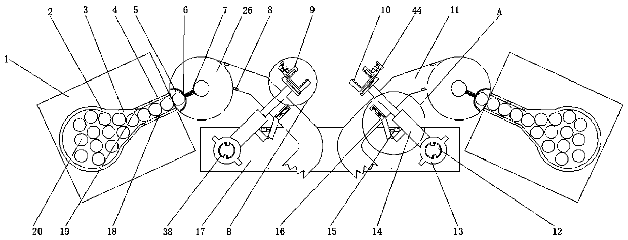
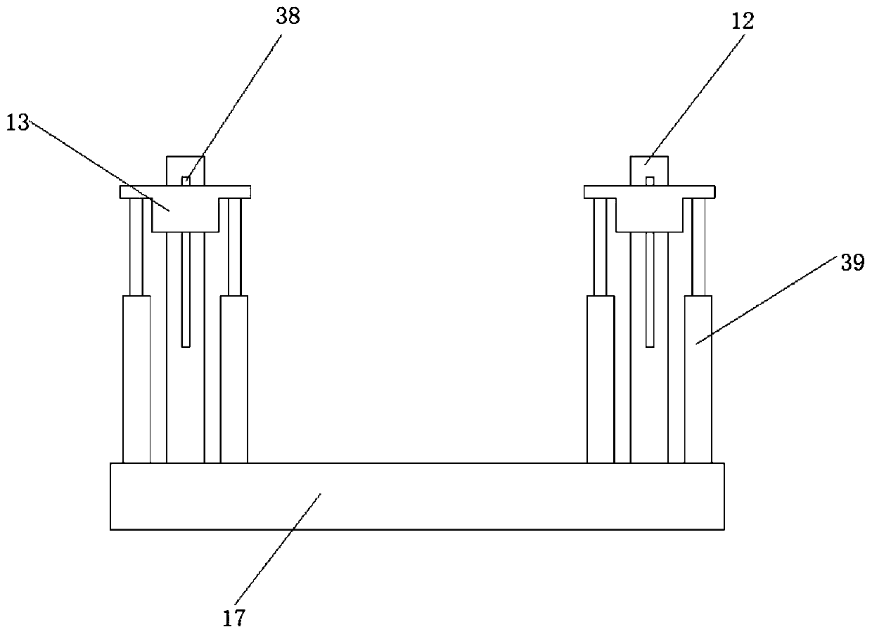
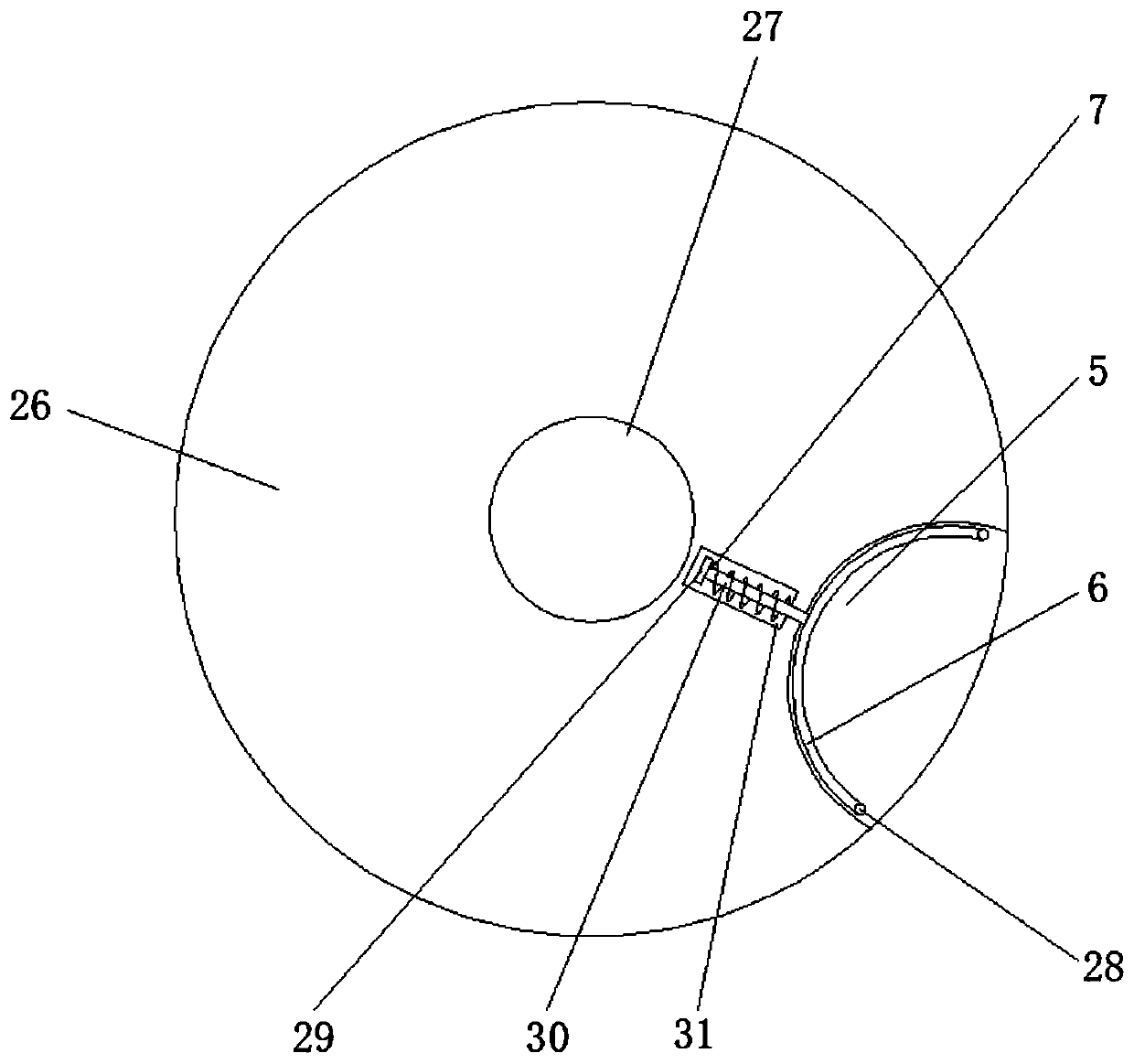
[0022] see Figure 1-6, an embodiment provided by the present invention: an automatic loading and unloading device for a milling machine, comprising a first conveyor belt 1, a guide column 12, a base 17 and a disc 26, and the two ends of the top of the base 17 are welded with a Guide column 12, the outer side of guide column 12 is provided with moving block 13, and the both sides of guide column 12 outer side walls are symmetrically provided with a pair of fir...


PUM


Abstract

The invention discloses an automatic milling machine feeding and charging device. The automatic milling machine feeding and charging device comprises first conveying belts, guiding columns, a base anddiscs. The guiding columns perpendicular to the base are connected to the two ends of the top of the base in a welding manner. A moving block is arranged on the outer side of each guiding column. A pair of first sliding grooves are symmetrically formed in the outer side wall of each guiding column. A sliding block is arranged on the inner side of each moving block, and each slide is matched withthe corresponding first slide groove. A pair of fixing lugs is symmetrically arranged on the two sides of the top of the outer side of each moving block. A pair of first extending-and-contracting rodsis symmetrically connected to the top of a first base on the outer side of each guiding rod in a welding manner, and each extending-and-contracting rod is parallel with the corresponding guide column. The outputting end of each first extending-and-contracting rod is connected with the corresponding fixing lug in a welding manner. The invention further provides a use method of the automatic milling machine feed and charging device. According to the automatic milling machine feeding and charging device, the same devices are symmetrically arranged on the left side and the right side of the base;working is conducted on the left side and the right side at the same time; automatic feeding and charging can be conducted on guiding column tools; the problem that danger is generated when feeding and discharging are conducted by workers; working is conducted on the devices on the left side and the right side at the same time; work efficiency is great improved.

Description

technical field [0001] The invention relates to the field of milling machine auxiliary devices, in particular to an automatic loading and unloading device for a milling machine. Background technique [0002] With the rapid development of the national economy and the continuous improvement of production efficiency, the degree of automation of modern industry is also constantly improving. In the field of modern automated production, it is very necessary to realize the automation of material handling, machine tool loading and unloading, especially for the automatic loading and unloading of guide column workpieces. [0003] At present, the existing traditional loading and unloading often requires workers to manually install the cylindrical workpiece on the workbench. The whole process requires a lot of physical strength and time, which greatly reduces production efficiency and is easy to cause danger. Contents of the invention [0004] The object of the present invention is t...

Claims


Application Information

Patent Timeline
IPC IPC(8): B23Q7/00B23Q7/04
CPCB23Q7/00B23Q7/04Y02P70/10
Inventor 饶静婷
Owner 聊城市技师学院
Why Eureka
Try Eureka