Combined-type submerged breakwater structure and manufacturing method thereof

A combined and submerged embankment technology, applied in the field of port and coastal engineering, can solve the problems of material waste, project cost, unstable submerged embankment structure, ecological environment damage, etc., and achieve low cost, ecological maintenance, and ecological significance. Effect

Pending Publication Date: 2019-08-30
HOHAI UNIV
View PDF0 Cites 5 Cited by
  • Summary
  • Abstract
  • Description
  • Claims
  • Application Information

AI Technical Summary

Problems solved by technology

[0006] The invention provides a combined submerged dike structure and its manufacturing method, which solves the technical problems of unstable submerged dike structure, complicated construction, waste of materials, high engineering cost, and damage to the ecological environment

Method used


Image

  • Combined-type submerged breakwater structure and manufacturing method thereof
  • Combined-type submerged breakwater structure and manufacturing method thereof
  • Combined-type submerged breakwater structure and manufacturing method thereof

Examples


Embodiment 1

[0034] Embodiment 1, the manufacturing method of combined submerged embankment structure

[0035] Step 1: Collect the wave height of the waves in the target sea area H ,wavelength L ,cycle T and water depth h The data.

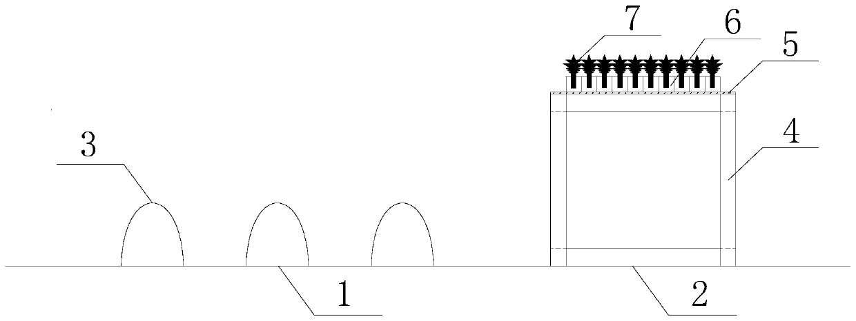
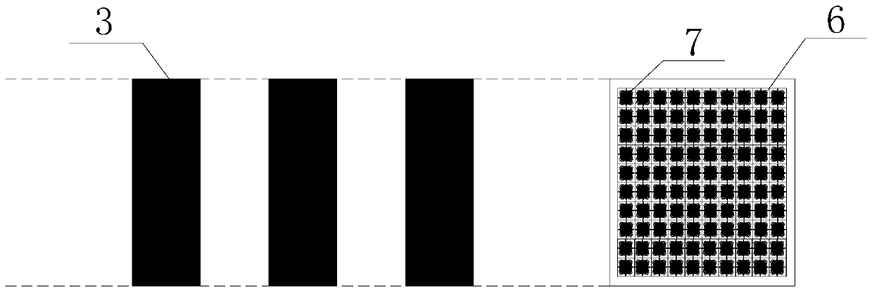
[0036] Step 2: Determine the size of the peak cylinder unit and the length of the peak cylinder unit based on the data in step 1 l Determined according to the length of the protective coast, the wavelength of the crest cylinder unit L b is the incident wavelength of waves in the target sea area L half of the amplitude of the crest cylinder element D and water depth h The ratio is 0.16;

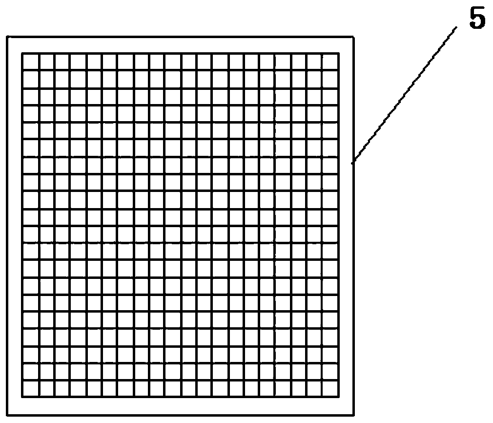
[0037] Step 3. In the target sea area, arrange the three prefabricated crest cylinders in step 2 in a periodic manner, and the distance between adjacently arranged wave crest cylinder units d with the wavelength of the crest cylinder unit L b Equal, the undulating extension direction of its periodic arrangement is consistent with the incident wave direction of the ...

Embodiment 2

[0041] Embodiment two, the manufacturing method of combined submerged embankment structure

[0042] Step 1: Collect the wave height of the waves in the target sea area H ,wavelength L ,cycle T and water depth h The data.

[0043] Step 2: Determine the size of the peak cylinder unit and the length of the peak cylinder unit based on the data in step 1 l Determined according to the length of the protective coast, the wavelength of the crest cylinder unit L b Equal to the incident wavelength of the waves in the target sea area L , the amplitude of the crest cylinder element D and water depth h The ratio is 0.18;

[0044] Step 3. In the target sea area, arrange the 4 crest cylinders prefabricated in step 2 in a periodic manner, and the distance between adjacently arranged wave crest cylinder units d with the wavelength of the crest cylinder unit L b Equal, the undulating extension direction of its periodic arrangement is consistent with the incident wave direction of th...


PUM


Abstract

The invention discloses a combined-type submerged breakwater structure. The combined-type submerged breakwater structure comprises a rigid submerged breakwater wave-blocking structure and a flexible plant wave-dissipating structure which are arranged side by side, and thus has a good wave dissipating effect; the rigid submerged breakwater wave-blocking structure is designed based on the Bragg resonance principle and has obvious wave preventing and bank protection effects; the flexible plant wave-dissipating structure adopts emergent flexible aquatic plants to dissipate waves, thus the water body environment can be significantly improved, and ecological benefits are maintained; and meanwhile, the flexible plant wave-dissipating structure is of a concrete frame structure and can form a goodsea water flow channel, and exchange of water bodies on the two sides and swimming of aquatic creatures are facilitated. The invention further discloses a manufacturing method of the combined-type submerged breakwater structure. After related data of a target sea area are collected, wave peak column body units are prefabricated and periodically arrayed, and then the flexible plant wave-dissipatingstructure is laid. The manufacturing method is low in cost, and construction is convenient; and practical value and ecological significance are both achieved.

Description

technical field [0001] The invention belongs to the technical field of port and coastal engineering, and in particular relates to a combined submerged embankment structure and a manufacturing method thereof. Background technique [0002] Coastal erosion causes a large amount of land loss, damage to coastal structures, and deterioration of the beach ecological environment, which has caused great harm to people's production, life, safety of life and property, and the ecological environment. The submerged embankment is a common hydraulic structure that protects the beach and promotes siltation. It has the functions of blocking the impact of waves and improving the scouring and silting conditions of the water area. Secondly, because it is an underwater structure, it does not affect the navigation of ships and maintains the beauty of the coast, so it is widely used in near-shore wave dissipation and siltation. [0003] The top surface and the upper part of the traditional riprap...

Claims


Application Information

Patent Timeline
IPC IPC(8): E02B3/06
CPCE02B3/066Y02A10/11
Inventor 陶爱峰苏俊玮涂俊豪刘亚伊徐啸王文婷
Owner HOHAI UNIV
Why Eureka
Try Eureka