Eureka AIR delivers breakthrough ideas for toughest innovation challenges, trusted by R&D personnel around the world.

Urea injection quantity control method and device

A technology of urea injection and control method, which is applied in the direction of electronic control of muffler, exhaust device, exhaust treatment device, etc., and can solve the problems of precise control of urea

Active Publication Date: 2019-08-30
WEICHAI POWER CO LTD
View PDF16 Cites 6 Cited by
  • Summary
  • Abstract
  • Description
  • Claims
  • Application Information

AI Technical Summary

Problems solved by technology

[0004] However, the control strategy for urea injection in the prior art cannot be figure 1 The shown aftertreatment system is based on the precise control of urea injection

Method used


Image

  • Urea injection quantity control method and device
  • Urea injection quantity control method and device
  • Urea injection quantity control method and device

Examples


Embodiment Construction

[0057] Exemplary embodiments of the present disclosure will be described in more detail below with reference to the accompanying drawings. Although exemplary embodiments of the present disclosure are shown in the drawings, it should be understood that the present disclosure may be embodied in various forms and should not be limited by the embodiments set forth herein. Rather, these embodiments are provided for more thorough understanding of the present disclosure and to fully convey the scope of the present disclosure to those skilled in the art.

[0058] It can be seen from the background technology that after adopting SCRF, the layout of the aftertreatment system is usually to arrange the SCR after the SCRF, and install a urea nozzle before the SCRF, specifically as figure 1 shown. However, the control strategy for urea injection in the prior art cannot be figure 1 The shown aftertreatment system is based on the precise control of urea injection.

[0059] In the embodimen...


PUM


Abstract

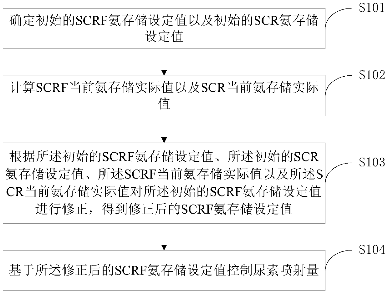
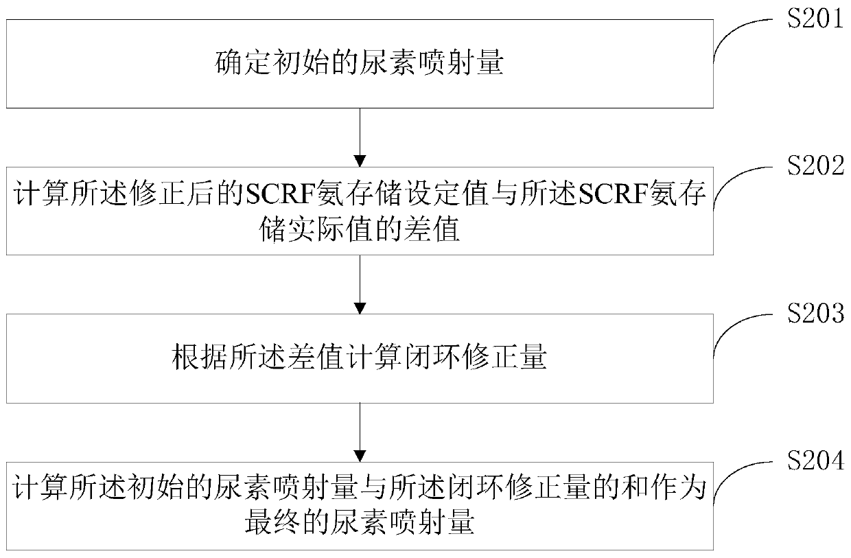
The application discloses a urea injection quantity control method and device. The urea injection quantity control method comprises the steps of determining an initial SCRF ammonia storage set value and an initial SCR ammonia storage set value; calculating an SCRF current ammonia storage actual value and an SCR current ammonia storage actual value; correcting the initial SCRF ammonia storage set value according to the initial SCRF ammonia storage set value, the initial SCR ammonia storage set value, the SCRF current ammonia storage actual value and the SCR current ammonia storage actual valueto obtain a corrected SCRF ammonia storage set value; and controlling the urea injection quantity based on the corrected SCRF ammonia storage set value. Through the above process, accurate control ofthe urea injection quantity can be realized.

Description

technical field [0001] The present application relates to the technical field of post-treatment systems, and more specifically, to a method and device for controlling the amount of urea injection. Background technique [0002] With the increasingly stringent automobile emission regulations, the aftertreatment system with SCR (selective catalyst reduction, selective catalytic reduction reactor) has become the mainstream technology for reducing emission pollution. The method of reducing emission pollution by the post-treatment system with SCR is to spray urea into the SCR tank to reduce nitrogen oxides, thereby reducing emissions and meeting the requirements of emission regulations. [0003] On the basis of SCR, the SCRF technology is further developed. SCRF refers to coating the SCR catalyst on the DPF (diesel particulate filter, particulate filter), also known as SCR on Filter, SDPF, etc. After adopting SCRF, the layout of aftertreatment system is usually to arrange SCR aft...

Claims


Application Information

Patent Timeline
Patent Type & Authority Applications(China)
IPC IPC(8): F01N3/20F01N9/00
CPCF01N3/208F01N9/00F01N2610/02Y02T10/12Y02T10/40
Inventor 张军张竞菲王国栋咸梦蝶
Owner WEICHAI POWER CO LTD
Why Eureka
Eureka Blog
Learn More