Air inlet valve for variable frequency screw air compressor

A technology for intake valves and air compressors, which is applied to mechanical equipment, machines/engines, liquid fuel engines, etc. It can solve problems such as fuel injection, inconvenient installation and maintenance, and noise generation, so as to improve action guidance and Sealing effect, cost reduction, and effect of leak point reduction

Pending Publication Date: 2019-08-30
南通市红星空压机配件制造有限公司
View PDF0 Cites 0 Cited by
  • Summary
  • Abstract
  • Description
  • Claims
  • Application Information

AI Technical Summary

Problems solved by technology

[0002] At present, most of the intake valves used in variable frequency oil-injected screw air compressors use conventional oil-injected screw machine intake valves. The structure of the intake valve is relatively complicated, some functions are wasted, and the cost is high, and the intake valve is cylindrical. When the compressor is running at low frequency, the check valve core will resonate and vibrate, resulting in noise, and oil injection is prone to occur at low frequency or when the compressor is stopped. The discharge valve and the intake valve body of the conventional intake valve are of separate design , a sealing ring needs to be configured between the two, and then locked with joints or bolts, which is inconvenient for installation and maintenance

Method used


Image

  • Air inlet valve for variable frequency screw air compressor
  • Air inlet valve for variable frequency screw air compressor
  • Air inlet valve for variable frequency screw air compressor

Examples


Embodiment Construction

[0022] In order to deepen the understanding of the present invention, the present invention will be further described below in conjunction with the embodiments and accompanying drawings. The embodiments are only used to explain the present invention and do not constitute a limitation to the protection scope of the present invention.

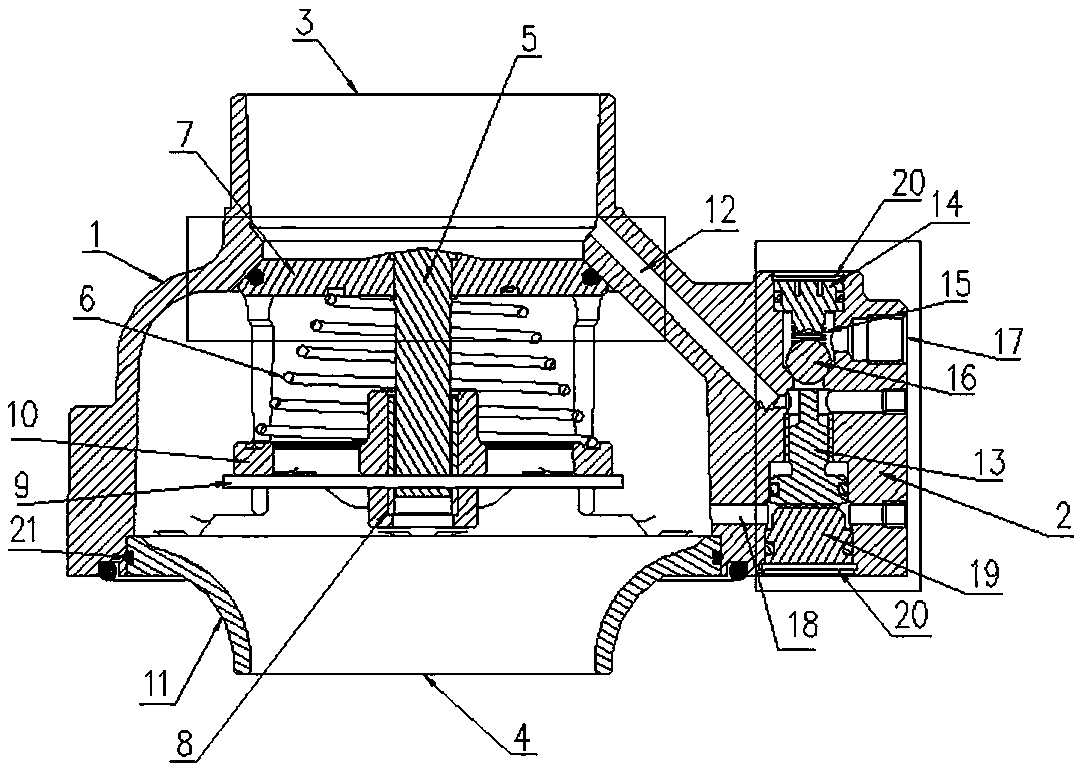
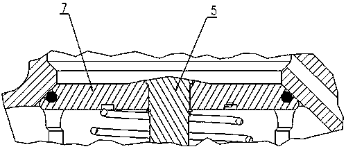
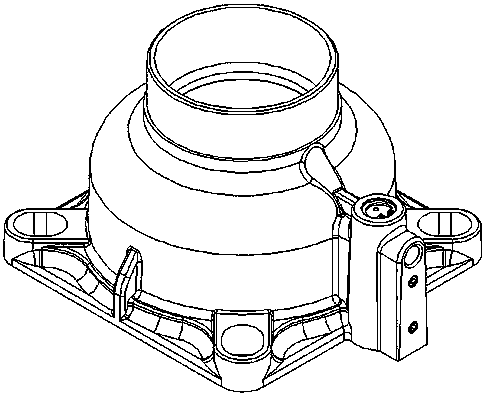
[0023] Such as Figure 1-3 It shows a specific embodiment of an intake valve for a variable frequency screw air compressor of the present invention: it includes an intake valve body 1, and a discharge valve body 2 is connected to one side of the intake valve body 1, The upper end of the intake valve body 1 is provided with an air inlet 3, and the lower end is provided with an oil deflector ring 11, and an exhaust port 4 is opened at the center of the oil deflector ring 11. A check valve rod 5, a check spring 6 and a check valve core 7 are arranged inside, and a check spring 6 is sleeved on the check valve rod 5, and the check spring 6 is a trunca...


PUM


Abstract

The invention discloses an air inlet valve for a variable frequency screw air compressor. The air inlet valve for the variable frequency screw air compressor comprises an air inlet valve body; one side of the air inlet valve body is connected with a discharge valve body; an air inlet is formed in the upper end of the air inlet valve body; an oil retaining ring is arranged at the lower end of the air inlet valve body; an exhaust opening is formed in the centre of the oil retaining ring; a check valve rod, a check valve spring and a check valve core are arranged in the air inlet valve body; thecheck valve spring is arranged on the check valve rod in a sleeving manner; a shaft sleeve is arranged at the lower end of the check valve rod in the sleeving manner; a stop ring is arranged outside the shaft sleeve; a supporting plate is arranged on the stop ring; a valve cover is arranged at the lower end of the discharge valve body; a discharge valve channel is arranged between the air inlet and the discharge valve body; an unloading valve core, a spring seat, a returning spring and a rubber ball are arranged in the discharge valve body; a discharge inlet is formed in one side of the upperend of the discharge valve body; and a discharge valve control opening is formed between the discharge valve body and the air inlet valve body. The air inlet valve for the variable frequency screw aircompressor is compact in structure and small in size, and has the advantages of checking stop, stopping discharge, preventing oil injection.

Description

technical field [0001] The invention relates to a combined valve, in particular to a combined valve integrated with an oil return check valve. Background technique [0002] At present, most of the intake valves used in variable frequency oil-injected screw air compressors use conventional oil-injected screw machine intake valves. The structure of the intake valve is relatively complicated, some functions are wasted, and the cost is high, and the intake valve is cylindrical. When the compressor is running at low frequency, the check valve core will resonate and vibrate, resulting in noise, and oil injection is prone to occur at low frequency or when the compressor is stopped. The discharge valve and the intake valve body of the conventional intake valve are of separate design , A sealing ring needs to be configured between the two, and then locked with joints or bolts, which is inconvenient for installation and maintenance. Contents of the invention [0003] The object of ...

Claims


Application Information

Patent Timeline
IPC IPC(8): F04C29/12F04C29/06F04C29/02F04C18/16F04C27/00F04C28/24
CPCF04C29/12F04C29/06F04C29/02F04C18/16F04C27/00F04C28/24
Inventor 张春荣郭子云
Owner 南通市红星空压机配件制造有限公司
Why Eureka
Try Eureka