Polarizer, electronic equipment and preparation method of polarizer

A technology of polarizers and linear polarizers, applied in optics, polarizing elements, optical elements, etc., can solve problems such as low transmittance of cameras, dust accumulation, cumbersomeness, etc., improve display quality, reduce the probability of dust accumulation, and facilitate the process Effect

Active Publication Date: 2019-08-30
KUNSHAN NEW FLAT PANEL DISPLAY TECH CENT +1
View PDF5 Cites 6 Cited by
  • Summary
  • Abstract
  • Description
  • Claims
  • Application Information

AI Technical Summary

Problems solved by technology

[0003] However, the polarizer will cause low transmittance of the camera installed on one side of the screen, so it is usually necessary to dig grooves on the polarizer corresponding to the position of the camera to form a depolarized area
[0004] The inventors of the present application found in the long-term research process that the above-mentioned method of forming the depolarization area is relatively cumbersome; and when the polarizer is attached to the cover plate in the later stage, the optical glue OCA cannot completely fill the gap formed by the digging in the polarizer , which in turn creates optical problems and may cause dust to accumulate in this recessed area

Method used


Image

  • Polarizer, electronic equipment and preparation method of polarizer
  • Polarizer, electronic equipment and preparation method of polarizer
  • Polarizer, electronic equipment and preparation method of polarizer

Examples


Embodiment Construction

[0028] The following will clearly and completely describe the technical solutions in the embodiments of the present application with reference to the drawings in the embodiments of the present application. Obviously, the described embodiments are only some of the embodiments of the present application, not all of them. Based on the embodiments in this application, all other embodiments obtained by persons of ordinary skill in the art without making creative efforts belong to the scope of protection of this application.

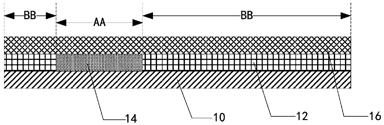
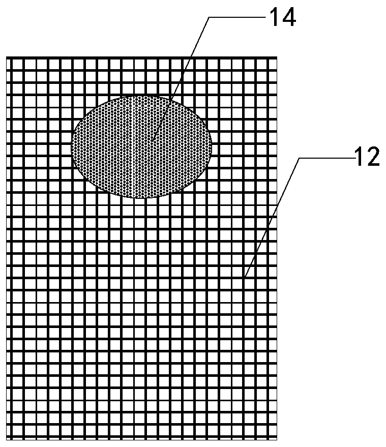
[0029] see Figure 1-Figure 2 , figure 1 It is a schematic structural diagram of an embodiment of a polarizer in the present application, figure 2 for figure 1 A schematic top view of an embodiment of a medium-transparent filler and a linear polarizing film. The polarizer includes a base film 10 , a linear polarizing film 12 , a transparent filler 14 and a retardation film 16 .

[0030] Specifically, one side surface of the base film 10 defines a first ar...


PUM


Abstract

The invention discloses a polarizer, electronic equipment and a preparation method of the polarizer. The polarizer comprises a basement membrane, a linearly polarizing film, a transparent filling bodyand a phase difference film, wherein a first region and a second region surrounding around the first region are defined on the surface of one side of the basement membrane; the linearly polarizing film is located on the surface of the side of the basement membrane and covers the second region; the transparent filling body is arranged at the same layer with the linearly polarizing film and coversthe first region; and the phase difference film covers the linearly polarizing film and one side, far away from the basement membrane, of the transparent filling body. By virtue of the way, the polarizer disclosed by the invention can relatively simply form a depolarized region.

Description

technical field [0001] The present application relates to the technical field of electronic devices, in particular to a polarizer, an electronic device and a method for preparing the polarizer. Background technique [0002] At present, electronic devices (such as mobile phones, tablets, TVs, etc.) have higher and higher requirements for the utilization rate of screen frames; in order to achieve a full-screen effect, the concept of a screen camera has emerged as the times require. In order to reduce the reflection of the metal layer in the electronic device to the external ambient light, it is generally necessary to install a polarizer on the screen to reduce the reflection of the metal layer to the external ambient light and improve the contrast of the electronic device under strong light. [0003] However, the polarizer will cause the camera installed on one side of the screen to have a low transmittance. Therefore, it is usually necessary to dig grooves on the polarizer co...

Claims


Application Information

Patent Timeline
Patent Type & Authority Applications(China)
IPC IPC(8): G02B5/30
CPCG02B5/30G02B5/3083G02B5/3041
Inventor 刘仁杰陈钢徐古胜陈玲艳张航
Owner KUNSHAN NEW FLAT PANEL DISPLAY TECH CENT
Why Eureka
Try Eureka