
A Calculation Method of Transmission Torque of Permanent Magnet Magnetic Coupler

A magnetic coupler, a technology for transmitting torque, applied in permanent magnet clutches/brakes, computer-aided design, electric brakes/clutches, etc. The effect of high efficiency and low time cost

Active Publication Date: 2020-09-25
DALIAN UNIV OF TECH
View PDF5 Cites 0 Cited by
  • Summary
  • Abstract
  • Description
  • Claims
  • Application Information

AI Technical Summary

Problems solved by technology

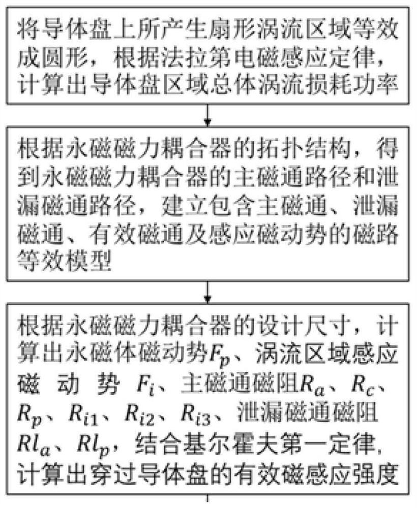
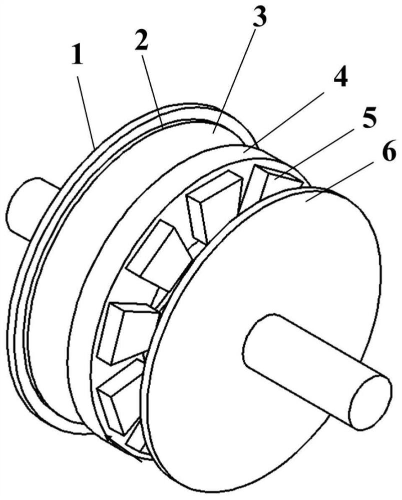
[0004] In order to overcome the defects of the prior art, the present invention invents a method for calculating the transmission torque of a permanent magnet magnetic coupler, which improves the defects of complex modeling and low calculation efficiency of the finite element calculation method, and is based on the topology of the permanent magnet magnetic coupler characteristics, build a magnetic circuit equivalent model including the main magnetic flux, leakage magnetic flux, effective magnetic flux and induced magnetomotive force, establish the magnetic circuit equivalent model equation, solve the effective magnetic induction intensity passing through the conductor disk, and analyze it through analytical calculations. Obtain the results of the permanent magnet magnetic coupling torque transmission

Method used


Image

  • A Calculation Method of Transmission Torque of Permanent Magnet Magnetic Coupler
  • A Calculation Method of Transmission Torque of Permanent Magnet Magnetic Coupler
  • A Calculation Method of Transmission Torque of Permanent Magnet Magnetic Coupler

Examples


Embodiment Construction

[0055] The present invention will be further elaborated below with reference to the accompanying drawings and embodiments.

[0056] In this embodiment, the transmission torque of a permanent magnet magnetic coupler with an input rotational speed of 1500 r / min and a 5-pole logarithm double-conductor disk symmetrical structure is selected for calculation.

[0057] Among them, the basic dimensions of the permanent magnet magnetic coupler with an input speed of 1500 r / min and a symmetrical structure of a double conductor disc with 5 magnetic pole pairs are: the size of the inner edge of the permanent magnet a=40mm, the size of the outer edge of the permanent magnet b=60mm, the diameter of the permanent magnet The vertical dimension to the edge L=57mm, the resistivity of the conductor plate ρ=1.75×10 -2 Ω mm 2 / m, the thickness of the conductor plate l c =6mm, vacuum permeability μ 0 =4π×10 -7 H / m, the relative permeability of the conductor disk μ rc = 0.999999, the pole dista...


PUM

PropertyMeasurementUnit
sizeaaaaaaaaaa
thicknessaaaaaaaaaa
lengthaaaaaaaaaa

Abstract

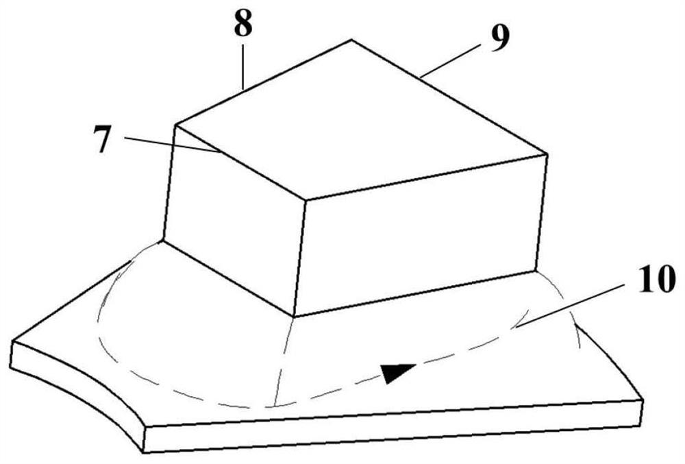
The invention relates to a method for calculating the transfer torque of a permanent magnet magnetic coupler, which belongs to the technical field of permanent magnet transmission, and relates to a method for calculating the transfer torque of a permanent magnet magnetic coupler. In this method, the fan-shaped eddy current area generated on the conductor disk is equivalent to a circle, and the total eddy current loss power in the conductor disk area is calculated according to Faraday's law of electromagnetic induction. According to the topological structure of the permanent magnet magnetic coupler, the equivalent model of the magnetic circuit including the main magnetic flux, the leakage magnetic flux, the effective magnetic flux and the induced magnetomotive force is established. According to the design dimensions of the permanent magnet magnetic coupler, the magnetomotive force of the permanent magnet, the induced magnetomotive force of the eddy current region, the main flux reluctance and the leakage flux reluctance are calculated. Combined with Kirchhoff's first law, the effective magnetic induction passing through the conductor disk is calculated. The transmission torque of the permanent magnet magnetic coupling is calculated and compared with the results of the finite element calculation method. This method is a calculation method with engineering practical application value, simple method, high calculation efficiency and low time cost.

Description

technical field [0001] The invention belongs to the technical field of permanent magnet transmission, and relates to a method for calculating the transmission torque of a permanent magnet magnetic coupler. Background technique [0002] With the continuous improvement of industrial level and scientific and technological strength, high-end equipment in the field of major national projects has put forward higher requirements for efficient and highly reliable transmission technology. Permanent magnet coupling transmission technology is widely used in petroleum, chemical, coal, electric power and other major projects due to its advantages of high efficiency and energy saving, strong environmental adaptability, good speed regulation performance, smooth start, overload protection, low cost and low vibration interference, etc. field. Among them, permanent magnetic coupling is an important classification of permanent magnetic coupling transmission technology. The effective calculati...

Claims


Application Information

Patent Timeline
Patent Type & Authority Patents(China)
IPC IPC(8): G06F30/23G06F30/17H02K49/10H02K49/04
CPCH02K49/102H02K49/108H02K49/046G06F30/17G06F30/23
Inventor 刘巍程习康刘思彤罗唯奇张洋周志龙逯永康贾振元
Owner DALIAN UNIV OF TECH
Learn More