Multi-channel power supply circuit based on magnetic particle magnetic control aggregation device

A technology of power supply circuit and magnetic particles, which is applied in the direction of circuits, output power conversion devices, magnets, etc.

Active Publication Date: 2019-08-30
CHONGQING UNIVERSITY OF SCIENCE AND TECHNOLOGY
View PDF4 Cites 0 Cited by
  • Summary
  • Abstract
  • Description
  • Claims
  • Application Information

AI Technical Summary

Problems solved by technology

Despite some research progress, there are still technical challen

Method used


Image

  • Multi-channel power supply circuit based on magnetic particle magnetic control aggregation device
  • Multi-channel power supply circuit based on magnetic particle magnetic control aggregation device
  • Multi-channel power supply circuit based on magnetic particle magnetic control aggregation device

Examples


Embodiment 1

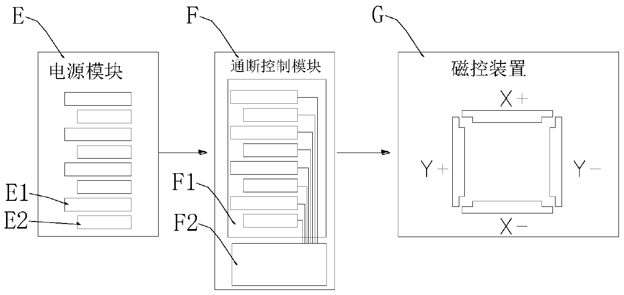
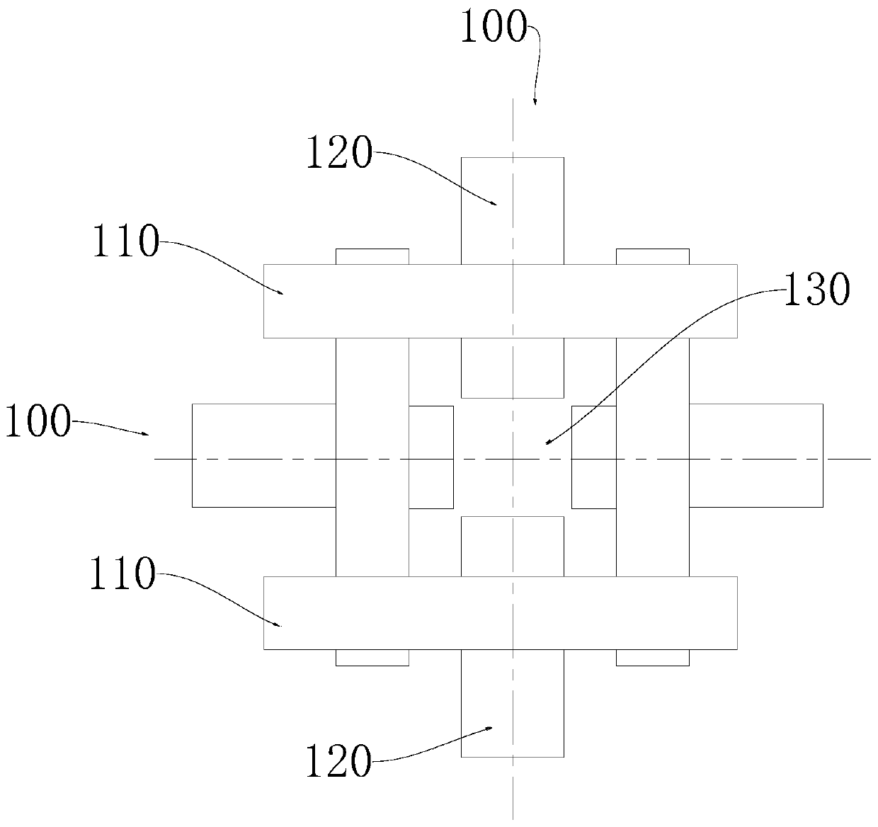
[0067] Such as Figure 2-5 As shown, a magnetic control device G is included, and the magnetic control device G is provided with at least two pairs of coil pairs 100;

[0068] Wherein, a pair of the coil pair 100 is provided with two groups of polarized coil groups, and one group of the polarized coil groups is provided with two sub-coils; the two sub-coils of the same group are arranged in parallel and facing each other, and the wires are wound in the same direction. , a unidirectional polarization zone is formed between the two sub-coils of the same group; the sub-coils of the two polarized coil groups of the same pair are parallel to each other, and the two polarized coil groups of the same pair The wires are wound in opposite directions, and the unidirectional polarization regions of the two polarized coil groups of the same pair cross each other to form a bidirectional polarization region;

[0069] The other pair of coils 100 is also provided with two push coils 120, the...

Embodiment 2

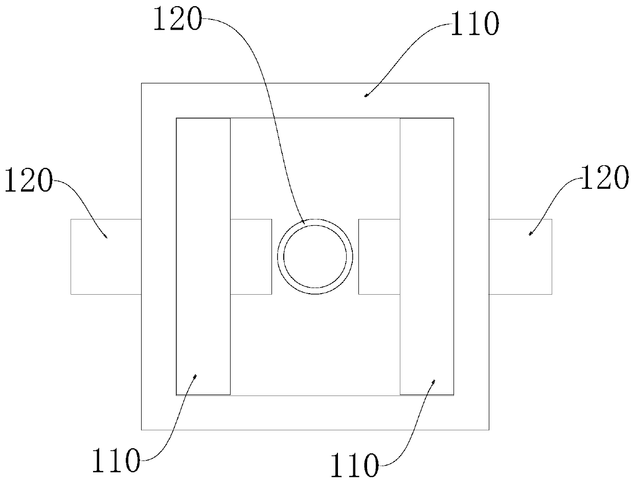
[0108] figure 2 with 3 A planar magnetron device is shown. There are two pairs of coils 100, and the centerlines of the two pairs of coils 100 are perpendicular to each other. A cube-shaped winding formwork is provided inside, and the polarized coil groups are all wound on the winding formwork, and the push coil 120 is threaded on the surface of the corresponding winding formwork. For the convenience of expression, the centerlines of the two groups of coil pairs 100 are respectively marked as x-axis and y-axis, and then there are two polarized-pushing coil groups with opposite driving directions on the x-axis and y-axis respectively. The polarized coil groups in the four driving directions are sequentially recorded as X+ polarized coil group, X-polarized coil group, Y+ polarized coil group and Y-polarized coil group, and the driving coils in the four driving directions are sequentially recorded as X+ Push Coil, X-Push Coil, Y+ Push Coil, and Y-Push Coil. The X+ polarized ...

Embodiment 3

[0111] Figure 5 Shown is a three-dimensional magnetic control device. There are three groups of coil pairs 100 , the three groups of coil pairs 100 enclose the cubic magnetic control area 130 , and the centerlines of the three coil pairs 100 are perpendicular to the center of the magnetic control area 130 . A square hollow winding formwork is provided inside, and the polarized coil groups are all wound on the winding formwork, and the driving coil 120 is threaded on the surface of the corresponding winding formwork.

[0112] For the convenience of expression, the centerlines of the three groups of coil pairs 100 are respectively marked as x-axis, y-axis and z-axis, and then two polarized-push coils with opposite driving directions are respectively arranged on the x-axis, y-axis and z-axis Group. The polarized coil groups in the six driving directions are sequentially recorded as X+ polarized coil group, X-polarized coil group, Y+ polarized coil group, Y-polarized coil group...


PUM

PropertyMeasurementUnit
Diameteraaaaaaaaaa

Abstract

The invention discloses a multi-channel power supply circuit based on a magnetic particle magnetic control aggregation device. The multi-channel power supply circuit comprises a power supply circuit and a power switch controller, the power supply circuit comprises at least two groups of voltage output circuits, each group of the voltage output circuits is at least provided with a pair of voltage output ends, and the voltage output ends supply power to the coils of all the magnetic control devices through power switches; the electric control output ends of the groups of electric control outputends of the power switch controller are correspondingly connected with coil power switch driving circuits one by one; and all the coil power switch driving circuits are connected with all the power switches in a one-to-one correspondence mode. The multi-channel power supply circuit based on a magnetic particle magnetic control aggregation device electrifies a polarized coil group and a pushing coil in each coil pair in sequence, and the interval time, the electrifying time and the electrifying voltage value can be adjusted.

Description

technical field [0001] The invention relates to the field of control of magnetic granular materials, in particular to a multi-channel power supply circuit based on a magnetic control aggregation device for magnetic particles. Background technique [0002] Magnetic particles, especially nano-magnetic particles, are new materials with rapid development and great application value in recent years. The wider the application. Nanomagnetic particles are generally composed of iron, cobalt, nickel and other metals and their oxides. In the medical field, they usually have a core-shell structure, consisting of a magnetic core and a polymer / silicon / hydroxyapatite wrapped outside the magnetic core. shell composition. The most common core layer consists of Fe with superparamagnetic or ferromagnetic properties 3 o 4 or γ-Fe 2 o 3 It has magnetic orientation, which means that the magnetic particles are targeted in the magnetic field environment. The magnetic particles can move in a ...

Claims


Application Information

Patent Timeline
IPC IPC(8): H02M3/158H01F1/12H01F1/20H01F7/20A61M37/00
CPCA61M37/00A61M2205/0272A61M2205/10H01F1/12H01F1/20H01F7/206H02M3/1582
Inventor 孙建春陈登明马毅龙邵斌郑元义周安若郭东林曾文杨棋棋何颖
Owner CHONGQING UNIVERSITY OF SCIENCE AND TECHNOLOGY
Why Eureka
Try Eureka