Adjustable perforating device for agricultural planting

A punching device, agricultural technology, applied in agriculture, planting method, application, etc., can solve problems such as low efficiency, and achieve the effect of improving punching accuracy

Inactive Publication Date: 2019-09-06
安利英
View PDF6 Cites 5 Cited by
  • Summary
  • Abstract
  • Description
  • Claims
  • Application Information

AI Technical Summary

Problems solved by technology

Among the agricultural machinery with fixed operations, there are two types: the movable type that can transfer the operating location in the non-operating state and the non-movable type that the operating location is always fixed. The traditional agricultural punching device uses manual punching, and manual punching Tools are used to dig holes, which is inefficient and depends on the operator's experience to control the punching spacing

Method used


Image

  • Adjustable perforating device for agricultural planting
  • Adjustable perforating device for agricultural planting
  • Adjustable perforating device for agricultural planting

Examples


Embodiment 1

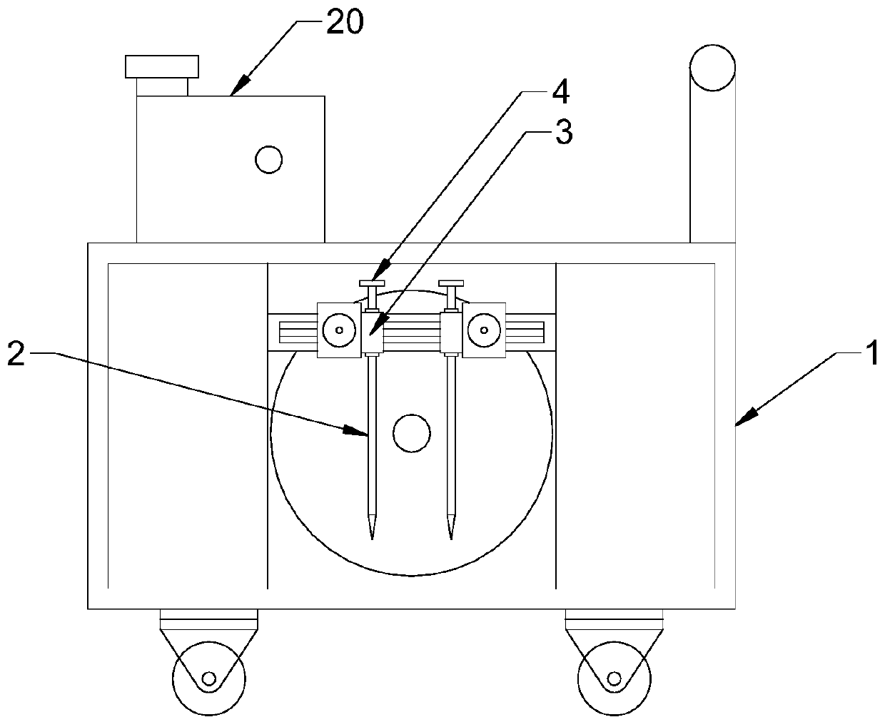
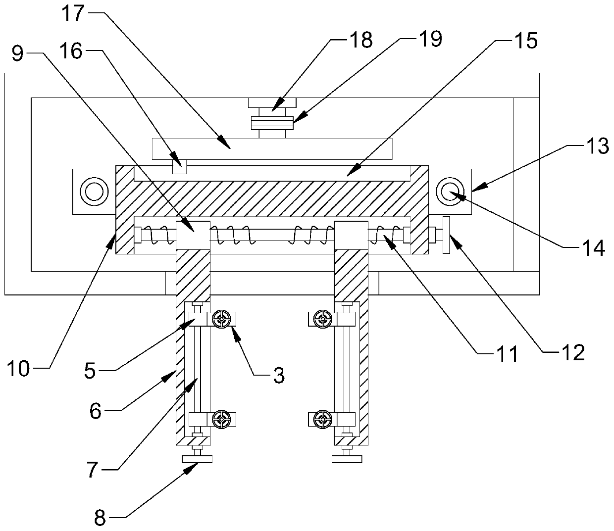
[0022] see Figure 1-5 , in an embodiment of the present invention, an adjustable punching device for agricultural planting, including a cart 1; two sets of punching rods 2 oppositely arranged on the outside of the cart 1, the lower ends of the punching rods 2 are tapered, Carry out punching; The upper end of the punching rod 2 is penetrated with a bearing block 3, the bearing block 3 is provided with a threaded through hole 301, and the punching rod 2 is provided with a thread matched with the threaded through hole 301; the top end of the punching rod 2 is fixed The depth adjustment wheel 4 is connected, and the depth adjustment wheel 4 is rotated to adjust the height of the punching rod 2, thereby adjusting the depth of punching.

[0023] The bearing block 3 is fixedly connected with a longitudinal slider 5, the longitudinal slider 5 is nested with a longitudinal chute plate 6, the longitudinal chute plate 6 is provided with a longitudinal chute, and the longitudinal chute i...

Embodiment 2

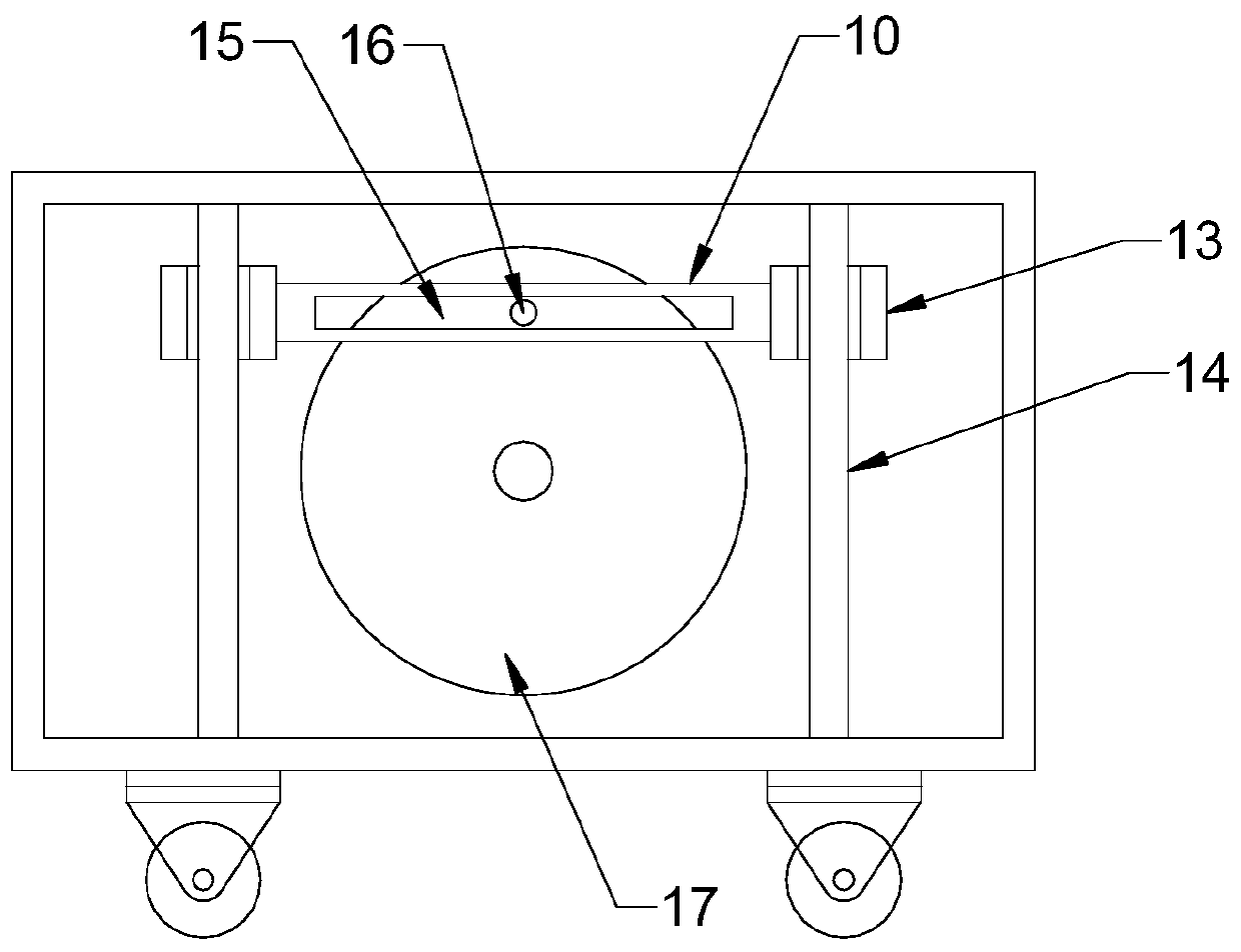
[0027] The difference between this embodiment and Embodiment 1 is that the lifting mechanism includes an eccentric disc 17, which is rotationally connected with the inner wall of the cart 1 through a fixed shaft 18; the front end of the eccentric disc 17 is fixedly connected with an eccentric column 16, which The rear end surface of the plate 10 is provided with a lifting chute 15 matched with the eccentric column 16. The lifting chute 15 is a rectangular chute arranged horizontally, and the eccentric column 16 is nested in the lifting chute 15; the fixed shaft 18 passes through the transmission belt 19 is connected to the output shaft of the driving device 20, the driving device 20 is a diesel engine, the driving device 20 drives the eccentric disc 17 to rotate, the eccentric column 16 drives the lifting plate 10 to reciprocate up and down along the guide rod 14, and the lifting plate 10 drives the punching rod 2 up and down Movement, punching, the operator pushes the cart 1 t...


PUM


Abstract

The invention discloses an adjustable perforating device for agricultural planting, comprising a cart. Two groups of perforating rods arranged relatively are arranged outside the cart; a carrier blockis arranged at the upper end of each perforating rod in penetrated manner; a longitudinal slider is fixedly connected to each carrier block; the corresponding longitudinal sliders are embedded in onelongitudinal slide-groove plate; a transverse slider is fixedly connected to the tail end of each longitudinal slide-groove plate; the transverse sliders are embedded in a lifting plate; the liftingplate is connected with a lifting mechanism. The carrier blocks in threaded connection with the perforating rods are provided, so that perforating depth is convenient to adjust; the transverse slidersand longitudinal sliders driven by bidirectional screws are provided, so that perforation transverse spacing and longitudinal spacing are convenient to adjust, and perforating precision and perforating efficiency are improved; an eccentric disc with the lifting plate and an eccentric post is provided, so that the perforating rods are driven to move up and down periodically to arrive at efficientperforating.

Description

technical field [0001] The invention relates to the field of agricultural planting, in particular to an adjustable punching device for agricultural planting. Background technique [0002] Agricultural and sideline products refer to the products formed by primary processing in planting, breeding, forestry, animal husbandry, aquaculture and other industries. In the process of agricultural planting, especially in the process of large-scale planting, drilling operations are required. The planting pit is convenient for subsequent rapid planting. According to the operation method, agricultural machinery can be divided into two categories: walking operation and fixed operation. Among the agricultural machinery for walking operations, there are two types of continuous walking types that operate during continuous travel and intermittent walking types that alternately travel and work. Among the agricultural machinery with fixed operations, there are two types: the movable type that c...

Claims


Application Information

Patent Timeline
IPC IPC(8): A01C5/04
CPCA01C5/04
Inventor 安利英
Owner 安利英
Why Eureka
Try Eureka