
Continuous mold for hardware punching

A technology of stamping dies and dies, which is applied in the field of continuous dies for metal stamping, can solve the problems of large number of labor and equipment, unsuitability for mass production, and low production efficiency, and achieve the goals of improving environmental protection, reducing pressure, and improving efficiency Effect

Pending Publication Date: 2019-09-06
张家港市云宸汽车零部件有限公司
View PDF0 Cites 2 Cited by
  • Summary
  • Abstract
  • Description
  • Claims
  • Application Information

AI Technical Summary

Problems solved by technology

[0002] In the process of hardware production and processing, engineering mold is an important link in hardware production and processing. Engineering mold refers to a mold that can only complete one stamping process in one stamping stroke. Take the product out of the mold, and then put it into the mold at the next station to continue production until the last process of the mold is finished, and the whole product is considered complete. This kind of mold needs to be converted by different machines, and the labor and equipment required The quantity is huge and the production efficiency is low, so it is not suitable for mass production
[0003] At the same time, when the existing stamping die processes the workpiece, the workpiece is easily bonded to the groove plate of the stamping die, and the staff needs to take it out manually, which has certain potential safety hazards

Method used


Image

  • Continuous mold for hardware punching
  • Continuous mold for hardware punching
  • Continuous mold for hardware punching

Examples


Embodiment Construction

[0017] The following will clearly and completely describe the technical solutions in the embodiments of the present invention with reference to the accompanying drawings in the embodiments of the present invention. Obviously, the described embodiments are only some, not all, embodiments of the present invention. Based on the embodiments of the present invention, all other embodiments obtained by persons of ordinary skill in the art without making creative efforts belong to the protection scope of the present invention.

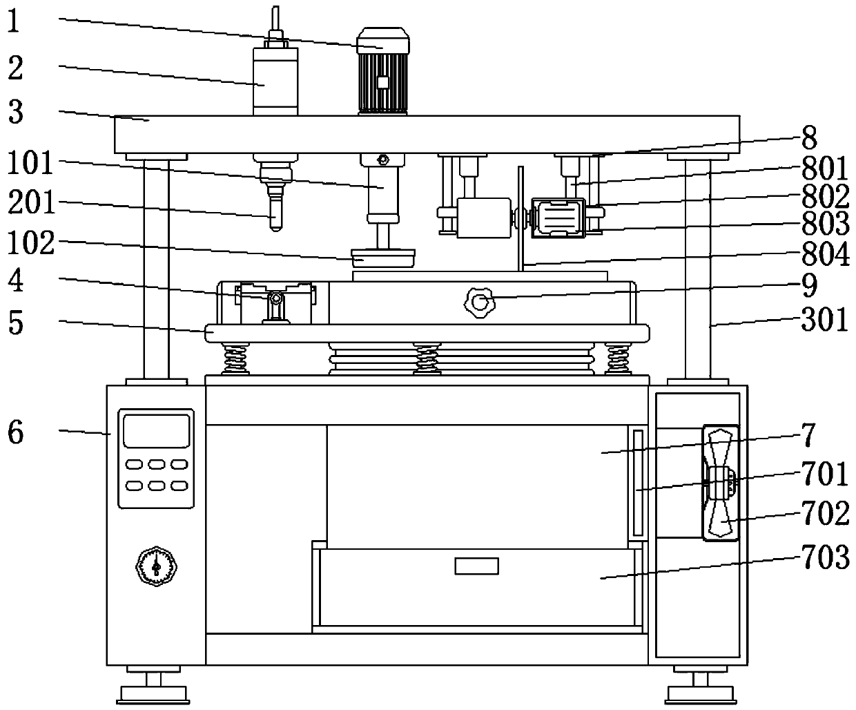
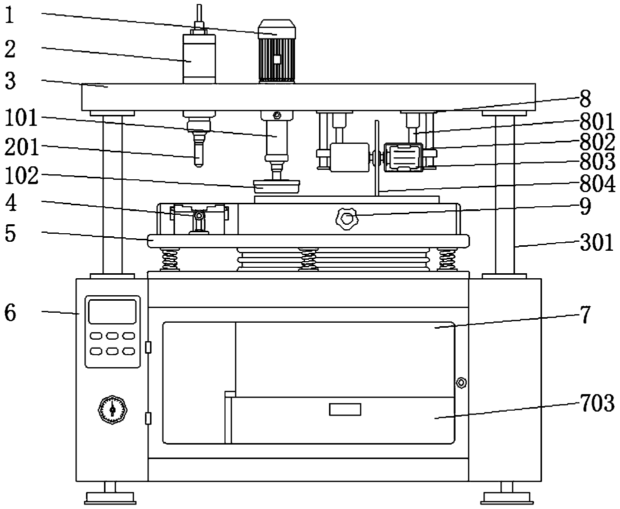
[0018] see Figure 1-4 , an embodiment provided by the present invention: a continuous die for metal stamping, including a stamping die 4, a bottom cabinet 6 and a cutting frame 8, the top of the bottom cabinet 6 is equipped with a buffer frame 5 through bolts, and two bottom cabinets 6 There are two sets of tripods welded on the side, the stable structure of the device can be increased through the tripods, and the stability of the device can be improved, and ...


PUM


Abstract

The invention discloses a continuous mold for hardware punching. The continuous mold for hardware punching comprises a punching mold, a bottom cabinet and a cutting rack. Mounting plates are welded totwo sides of the top of the bottom cabinet through supporting rods, a penetrating air cylinder is fixedly mounted on the tops of the mounting plates, a motor is fixedly mounted on the side, far awayfrom the air cylinder, of the top of the mounting plate, the cutting rack is fixedly mounted at the bottom of the mounting plate through a bolt, a buffer rack is mounted on the top of the bottom cabinet through a bolt, a punching mold is fixedly mounted on one side of the top of the buffer rack, and a fixing rack is fixedly mounted on one side of the punching mold. The continuous mold is providedwith a reset rack, so that a trough plate of the mold is reset, the punched mold is taken out conveniently, and a workpiece is prevented from being adhered to the trough plate of the punching mold, sothat the punching efficiency of the device is improved effectively. The workpiece can be polished through a mounted polishing disc, so that staff does not need to polish with additional equipment, sothat the functionality of the continuous mold is increased and the practicality of the continuous mold is improved.

Description

technical field [0001] The invention relates to the technical field of metal molds, in particular to a continuous mold for metal stamping. Background technique [0002] In the process of hardware production and processing, engineering mold is an important link in hardware production and processing. Engineering mold refers to a mold that can only complete one stamping process in one stamping stroke. Take the product out of the mold, and then put it into the mold at the next station to continue production until the last process of the mold is finished, and the whole product is considered complete. This kind of mold needs to be converted by different machines, and the labor and equipment required The quantity is huge and the production efficiency is low, so it is not suitable for mass production. [0003] At the same time, when the existing stamping die is processing the workpiece, the workpiece is easily bonded to the groove plate of the stamping die, which needs to be manual...

Claims


Application Information

Patent Timeline
IPC IPC(8): B21D37/08B21D28/14B24B55/06B24B41/06
CPCB21D37/08B21D28/14B24B55/06B24B41/065
Inventor 陆益辉张敏李凤祥
Owner 张家港市云宸汽车零部件有限公司
Learn More