
Thermal transfer printing coding machine and motor rotating speed control method and device thereof

A speed control and motor technology, applied in printing devices, printing, etc., can solve the problems of cumbersome, complicated structure and program control, complicated angular velocity measurement and calibration methods, etc.

Active Publication Date: 2019-09-06
XIAMEN HANIN ELECTRONICS TECH CO LTD
View PDF5 Cites 8 Cited by
  • Summary
  • Abstract
  • Description
  • Claims
  • Application Information

AI Technical Summary

Problems solved by technology

The disadvantage is that two sets of sensors are required, and the structure and program control are more complicated
[0005] The patent document CN102958702B discloses a belt drive and a method of operating the belt drive, and specifically discloses that a sensor assembly is added in the drive to obtain the angular velocity of the carbon ribbon motor and the carbon ribbon motor. Among them, CN102958702B further discloses that the sensor assembly includes A set of corresponding hall chips and magnetic components set on the tension adjustment device, and through the cooperation of Hall chips and magnetic components to realize the measurement of the angular velocity of the carbon ribbon motor and the carbon ribbon motor, as well as the carbon on the belt path. Control with length, but the angular velocity measurement and calibration method of Comparative Document 1 is more complicated and cumbersome

Method used


Image

  • Thermal transfer printing coding machine and motor rotating speed control method and device thereof
  • Thermal transfer printing coding machine and motor rotating speed control method and device thereof
  • Thermal transfer printing coding machine and motor rotating speed control method and device thereof

Examples


Embodiment Construction

[0044] The following will clearly and completely describe the technical solutions in the embodiments of the present invention with reference to the accompanying drawings in the embodiments of the present invention. Obviously, the described embodiments are only some, not all, embodiments of the present invention. Based on the embodiments of the present invention, all other embodiments obtained by persons of ordinary skill in the art without creative efforts fall within the protection scope of the present invention.

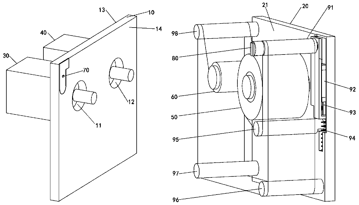
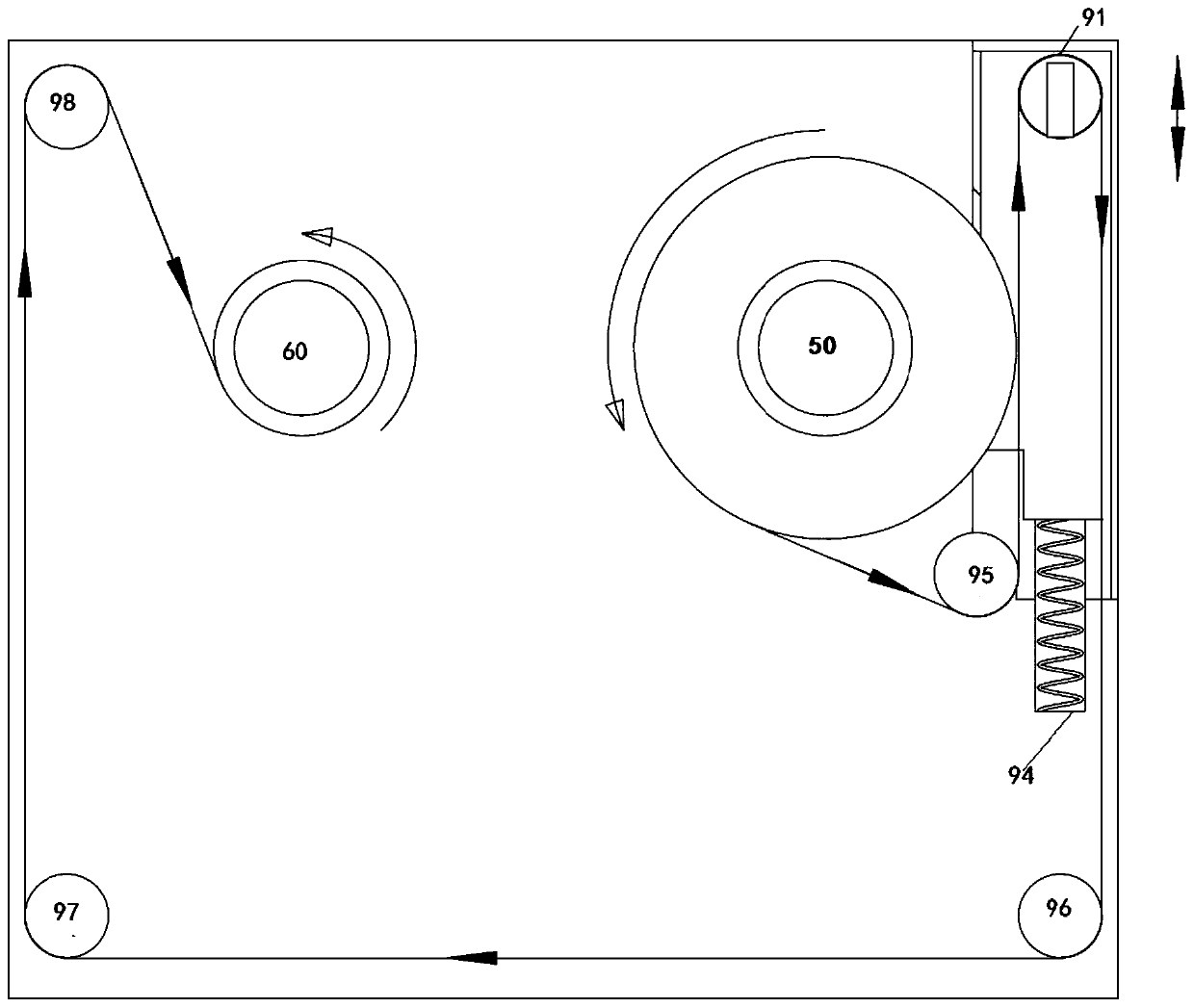
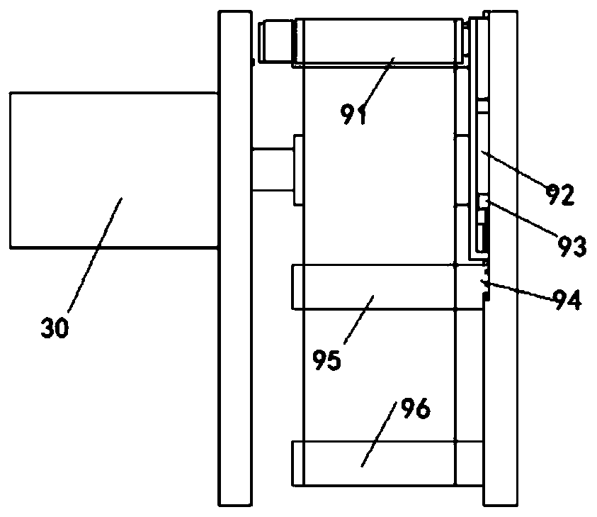
[0045] see figure 1 , the first embodiment of the present invention provides a thermal transfer coding machine, which includes a first fixed plate 10, a second fixed plate 20, a first motor 30, a second motor 40, a tension adjustment assembly, a first ribbon The reel 50, the second carbon ribbon reel 60, the Hall chip 70, the magnetic element 80 and the controller; wherein, the first carbon ribbon reel 50, the second carbon ribbon reel 60, and the tension adjustmen...


PUM


Abstract

The invention discloses a thermal transfer printing coding machine and a motor rotating speed control method and device thereof. The method comprises the following steps: detecting the position of a magnetic element; driving a second motor used for recovering thermal transfer ribbons to recover the thermal transfer ribbons based on the position until the second end of the magnetic element is aligned with a hall chip; recording the rotating angle of the second motor; driving a first motor used for distributing the thermal transfer ribbons to distribute the thermal transfer ribbons based on theposition until the first end of the magnetic element is aligned with the hall chip; recording the rotating angle of the first motor; calculating the first radius of the first thermal transfer ribbonscorresponding to the first motor and the second radius of the second thermal transfer ribbons corresponding to the second motor based on the recorded rotating angle of the second motor, the rotating angle of the first motor, and the length of the magnetic element; and acquiring the target angular speed of the first motor and the target angular speed of the second motor based on the first radius, the second radius and the preset thermal transfer ribbon running speed. With the adoption of the method, the motor angle speed can be conveniently measured and controlled, and thus the linearity speedand proper tension of the thermal transfer ribbons can be ensured.

Description

technical field [0001] The invention relates to the technical field of printing, in particular to a thermal transfer coding machine and its motor speed control and device. Background technique [0002] The thermal transfer coding machine heats the ribbon through the print head to transfer the ink to the medium to achieve clear printing of the content. A thermal transfer printer generally includes a carbon ribbon reel and a carbon ribbon reel, which are driven by their own motors. Since the carbon ribbon is very thin, it is very important to ensure that the tension of the carbon ribbon extending between the carbon ribbon reel and the carbon ribbon reel is kept within a certain range. If the tension is too high, the carbon ribbon will be deformed or broken. result in incorrect operation or affect print quality. [0003] As the printing progresses, the carbon ribbon is gradually transferred from the carbon ribbon reel to the carbon ribbon reel, the diameter of the carbon ribb...

Claims


Application Information

Patent Timeline
Patent Type & Authority Applications(China)
IPC IPC(8): B41J2/325B41J29/393
CPCB41J2/325B41J29/393Y02P70/10
Inventor 不公告发明人
Owner XIAMEN HANIN ELECTRONICS TECH CO LTD
Learn More