Pneumatic rotary suction nozzle

A rotary and pneumatic technology, applied in the field of pneumatic rotary suction nozzle device, can solve the problems of reducing the reliability of the feeding mechanism, the existence of safety hazards, and the large size of the suction nozzle, so as to simplify the feeding mechanism and its control system, Improve the reliability and safety, the effect of safe and environmentally friendly material transportation

Inactive Publication Date: 2019-09-06
CENT SOUTH UNIV
View PDF3 Cites 0 Cited by
  • Summary
  • Abstract
  • Description
  • Claims
  • Application Information

AI Technical Summary

Problems solved by technology

At present, the feeding mechanism used is motor-driven or hydraulic-driven, which makes the structure of the suction nozzle larger and more complicated.
For the electric-driven external feeding mechanism, an external power supply is required, in addition to generating additional energy consumption in addition to material suction in the pipeline, there are also potential safety hazards
Similarly, in addition to extra energy consumption, the hydraulic feeding mechanism also has pollution problems caused by oil leakage
The complex structure of the two also reduces the reliability of the feeding mechanism, which in turn leads to the failure of suction

Method used


Image

  • Pneumatic rotary suction nozzle

Examples


Embodiment Construction

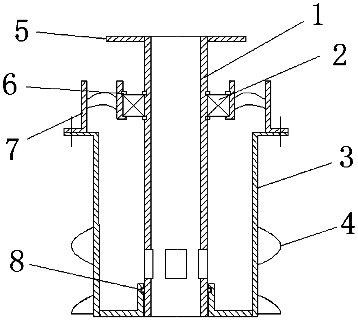
[0009] Such as figure 1 As shown, the inner cylinder (1) and the flange (5) are connected by welding, the turbine blades are welded between the inner and outer cylinders of the turbine (7), and the inner ring of the turbine (7) and the inner cylinder of the suction nozzle are slewing (2) Connect to ensure the rotation of the turbine (7) relative to the inner cylinder (1), the slewing bearing (2) is limited by the bearing stop ring (6), and the outer cylinder (3) and the turbine (7) are connected by screws The fixed connection is connected with the spiral blade (4) and the outer wall of the outer cylinder (3) by welding. Both the turbine (7) and the outer wall of the outer cylinder (3) have a flange structure, and their joint surfaces should be equipped with sealing rings to ensure their airtightness through screw connections.

[0010] When the material is sucked, the air flow enters the outer cylinder from the turbine (7), and due to the action of the air flow, the turbine 7 ...


PUM


Abstract

The invention discloses a pneumatic rotary suction nozzle. The invention discloses a pneumatic rotary suction nozzle device adopting a suction conveying manner. The pneumatic rotary suction nozzle device adopting the suction conveying manner comprises an inner barrel, a turbine, an outer barrel, a rotary bearing and other structures, wherein the outer barrel is fixedly connected with the turbine;the turbine and the inner barrel are mutually supported through the rotary bearing; the turbine and the outer barrel form an intake channel; the turbine sucks gas to generate rotary movement; the outer barrel is driven to rotationally stir materials to break a hardened state and improve the flowability of the materials; and meanwhile, the sucked gas enters the inner barrel through an air supplementing port in the wall of the inner barrel, and the materials at the bottom of the inner barrel are driven to be sucked into the barrel to realize the function of the suction nozzle. The pneumatic rotary suction nozzle is simple in structure, has no external energy, and is safe and environment-friendly.

Description

technical field [0001] The invention relates to a suction device, in particular to a pneumatic rotary suction nozzle device. Background technique [0002] The suction nozzle is mainly used for negative pressure conveying of powder and small particle materials, which can smoothly suck the material into the pipeline for transportation. The existing suction nozzles are single-tube and double-tube. The feeding mechanism is installed on the outer end of the mouth, and the feeding mechanism is driven to rotate by external power to improve the fluidity of the material. The currently used feeding mechanism is motor-driven or hydraulically driven, which makes the structure of the suction nozzle larger and more complicated. For the electric-driven external material feeding mechanism, an external power supply is required, in addition to generating additional energy consumption in addition to material suction in the pipeline, there are also potential safety hazards. Similarly, in addi...

Claims


Application Information

Patent Timeline
IPC IPC(8): B65G53/42
CPCB65G53/42
Inventor 柳波李东晖刘镇业张晓仪
Owner CENT SOUTH UNIV
Why Eureka
Try Eureka