Continuous cotton spun fiber rolling equipment

A continuous cotton spinning technology, applied in the field of light textiles, can solve the problems of poor yarn stretchability, thick yarn, low strength, etc., and achieve the effects of short production intervals, simple and clear operation, and high kinetic energy utilization

Active Publication Date: 2019-09-06
NANTONG JINSHAN TEXTILE
View PDF6 Cites 0 Cited by
  • Summary
  • Abstract
  • Description
  • Claims
  • Application Information

AI Technical Summary

Problems solved by technology

[0002] As we all know, modern textile refers to the multi-scale structure processing technology of a kind of fiber or fiber aggregate, and because the cotton spinning process has high production capacity, low price and relatively simple process, cotton spinning occupies the leading position in the textile industry; the traditional ones currently on the market Cotton spun threads are all solid spun threads, which are thick and heavy, and have poor versatility in some special scenarios; at the same time, traditional cotton spun threads are generally horizontal, with poor stretchability and low strength; in addition, traditional Cotton yarn production equipment requires a lot of manual operations, which is complicated and cumbersome, which not only increases the work intensity of workers, but also makes the produced yarn poor in integrity and low in quality; therefore, it is necessary to design a continuous Cotton spinning fiber rolling equipment to solve the above problems

Method used


Image

  • Continuous cotton spun fiber rolling equipment
  • Continuous cotton spun fiber rolling equipment
  • Continuous cotton spun fiber rolling equipment

Examples


Embodiment Construction

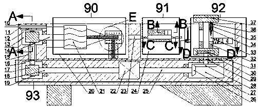
[0027] Combine below Figure 1-6 The present invention is described in detail, and for convenience of description, the orientations mentioned below are now stipulated as follows: figure 1 The up, down, left, right, front and back directions of the projection relationship itself are the same.

[0028] combined with Figure 1-6 The described continuous cotton spinning fiber rolling equipment includes a fuselage 10, and the knitting chamber 20 with an upward opening is arranged in the fuselage 10;

[0029] The weaving chamber 20 is provided with a helical weaving mechanism 90 for weaving cotton fibers into helical yarns. The helical weaving mechanism 90 includes the weaving chamber 20, and a first transmission mechanism is arranged in the left end wall of the weaving chamber 20. chamber 13, a first rotating shaft 14 is rotated between the first transmission chamber 13 and the braiding chamber 20, and a helical winding wheel 21 is fixed on the first rotating shaft 14 in the brai...


PUM


Abstract

The invention discloses continuous cotton spun fiber rolling equipment which comprises an equipment body. A weaving cavity with an upward opening is formed in the equipment body, a spiral weaving mechanism for weaving cotton spun fiber into spiral yarn is arranged in the weaving cavity and comprises the weaving cavity, a first transmission cavity is formed in the left-side end wall of the weavingcavity, a first rotating shaft is rotatably arranged between the first transmission cavity and the weaving cavity, and a spiral winding wheel is fixedly arranged on the first rotating shaft in the weaving cavity. The cotton spun fiber is spirally wound to form spiral spun yarn which is hollow, so that the spun yarn is light in weight and wide in application range; inside spiral structure of the spiral spun yarn is fixed by utilizing glass glue, so that the spun yarn produced by the equipment is high in strength and quality; in the process of production, the equipment can realize continuous production, is short in production interval and high in production efficiency and kinetic energy utilization rate and is simple and clear in operation when a drum is replaced for production.

Description

technical field [0001] The invention relates to the field of light textiles, in particular to continuous cotton spinning fiber rolling equipment. Background technique [0002] As we all know, modern textile refers to the multi-scale structure processing technology of a kind of fiber or fiber aggregate, and because the cotton spinning process has high production capacity, low price and relatively simple process, cotton spinning occupies the leading position in the textile industry; the traditional ones currently on the market Cotton spun threads are all solid spun threads, which are thick and heavy, and have poor versatility in some special scenarios; at the same time, traditional cotton spun threads are generally horizontal, with poor stretchability and low strength; in addition, traditional Cotton yarn production equipment requires a lot of manual operations, which is complicated and cumbersome, which not only increases the work intensity of workers, but also makes the prod...

Claims


Application Information

Patent Timeline
Patent Type & Authority Applications(China)
IPC IPC(8): D02G3/22D02G3/40
CPCD02G3/22D02G3/40
Inventor 帅向芳
Owner NANTONG JINSHAN TEXTILE
Why Eureka
Try Eureka