On-line monitoring system for hump signal device and online monitoring method for reducer

A technology of signal equipment and monitoring system, which is applied in the field of on-line monitoring system of hump signal equipment, can solve problems affecting system operation and maintenance, on-site fault location, troublesome troubleshooting, lack of electrical parameter record data, etc., to achieve real-time monitoring and convenient data Record, facilitate the effect of failure analysis

Pending Publication Date: 2019-09-06
HENAN SPLENDOR SCI & TECH
View PDF0 Cites 7 Cited by
  • Summary
  • Abstract
  • Description
  • Claims
  • Application Information

AI Technical Summary

Problems solved by technology

[0003] 1. At present, the real-time online monitoring of the electrical parameters of the signal equipment at the hump station is in a vacant state, which leads to the hidden dangers of the early failure of the signal equipment that cannot be discovered in time, and when the signal equipment fails, there is a lack of electrical parameter record data before and after the failure, which can locate the on-site fault. Troubleshooting causes a lot of trouble and seriously affects the efficiency of on-site troubleshooting
[0004] 2. The daily maintenance of signal equipment in the on-site

Method used


Image

  • On-line monitoring system for hump signal device and online monitoring method for reducer
  • On-line monitoring system for hump signal device and online monitoring method for reducer
  • On-line monitoring system for hump signal device and online monitoring method for reducer

Examples


Embodiment 1

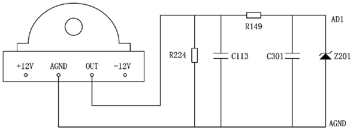
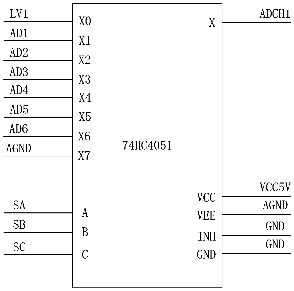
[0040] Such as figure 2 As shown, in view of the fast action of the ZK4 electro-pneumatic switch machine and the characteristics of the current value of the solenoid valve as a small signal DC, the current detection circuit at the sending end of the solenoid valve in this embodiment includes a perforated Hall current transformer, and according to the safety design principle, a perforated Hall current transformers are used to collect raw data, and the sampling locations are as follows Figure 8 As shown in the figure, pass the sending end line (i.e. the input side line) of the solenoid valve on the electropneumatic switch machine through the middle of the perforated Hall current transformer. The perforated Hall current transformer needs ±12V power supply, and the output of the perforated Hall current transformer After filtering and voltage stabilization, the analog multiplexer 74HC4051 is output to the AD port of the DSP, and the acquisition is completed by the DSP. The pin co...

Embodiment 2

[0054] In this embodiment, the functional design of the monitoring method includes:

[0055] 1. Real-time monitoring of the braking time and release time of the reducer, and timely alarm for time exceeding the limit.

[0056] 2. Real-time monitoring of the sending terminal voltage and solenoid valve current of the reducer equipment at the distribution board, and forming reports and curves, and timely alarming of the sending terminal voltage, solenoid valve current exceeding the limit and abnormal mutation.

[0057] In this embodiment, the speed reducer includes a brake relay, a release relay, a brake indication relay and a release indication relay, and the status of these relays is monitored. The status monitoring design includes: using the empty contacts of these four relays to collect their real-time status, That is, a special power supply 24V+ is connected to the middle contact of the empty contact, and whether there is 24V+ on the upper and lower contacts is collected in r...


PUM


Abstract

The invention provides an on-line monitoring system for a hump signal device and an online monitoring method for a reducer. A current detecting circuit of an electromagnetic valve transmitting terminal and a voltage detecting circuit of a relay empty idle contact are arranged to monitor a working current of a solenoid valve of a signal device and states of all relays continuously in real time; andthen whether relevant operational indicators of the signal device meet the requirements is determined based on monitoring results to realize real-time monitoring of the signal device and carry out data recording and fault analysis conveniently. According to the invention, the reducer is monitored and a transmitting terminal current of the solenoid valve, a brake relay state, a remission relay state, a brake indicating relay state, and a remission indicating relay state are obtained; whether the voltage and current are normal and the brake time and remission time are exceeded are determined based on the monitoring results; and a fault location is determined based on the determination results to realize real-time monitoring of the reducer.

Description

technical field [0001] The invention relates to the field of rail traffic monitoring, in particular to an online monitoring system for hump signal equipment and an online monitoring method for a reducer. Background technique [0002] With the gradual realization of hump automation in my country's marshalling stations, the daily maintenance of hump signal equipment has become increasingly prominent, and there are mainly the following outstanding problems: [0003] 1. At present, the real-time online monitoring of the electrical parameters of the signal equipment at Hump Station is in a vacant state, which leads to the hidden dangers of the early failure of the signal equipment that cannot be discovered in time, and when the signal equipment fails, there is a lack of electrical parameter record data before and after the failure, so as to locate the on-site fault, Troubleshooting causes a lot of trouble and seriously affects the efficiency of on-site troubleshooting. [0004] ...

Claims


Application Information

Patent Timeline
IPC IPC(8): G01R31/00G01R31/327G01R19/165G01R19/25B61K9/08
CPCB61K9/08G01R19/16528G01R19/25G01R31/00G01R31/327
Inventor 刘伟徐大贵张成斌
Owner HENAN SPLENDOR SCI & TECH
Why Eureka
Try Eureka