Online monitoring system for hump signal device and online monitoring method for switch machine

A technology of signal equipment and monitoring system, applied in the field of on-line monitoring system of hump signal equipment, which can solve problems such as on-site fault location, troublesome troubleshooting, lack of electrical parameter record data, hidden danger of signal equipment failure can not be discovered in time, etc., so as to facilitate failure Analysis, the effect of convenient data recording

Pending Publication Date: 2019-09-06
HENAN SPLENDOR SCI & TECH
View PDF0 Cites 3 Cited by
  • Summary
  • Abstract
  • Description
  • Claims
  • Application Information

AI Technical Summary

Problems solved by technology

[0003] 1. At present, the real-time online monitoring of the electrical parameters of the signal equipment at the hump station is in a vacant state, which leads to the hidden dangers of the early failure of the signal equipment that cannot be discovered in time, and when the signal equipment fails, there is a lack of electrical parameter record data before and after the failure, which can locate the on-site fault. Troubleshooting causes a lot of trouble and seriously affects the efficiency of on-site troubleshoo

Method used


Image

  • Online monitoring system for hump signal device and online monitoring method for switch machine
  • Online monitoring system for hump signal device and online monitoring method for switch machine
  • Online monitoring system for hump signal device and online monitoring method for switch machine

Examples


Embodiment 1

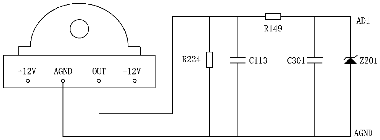
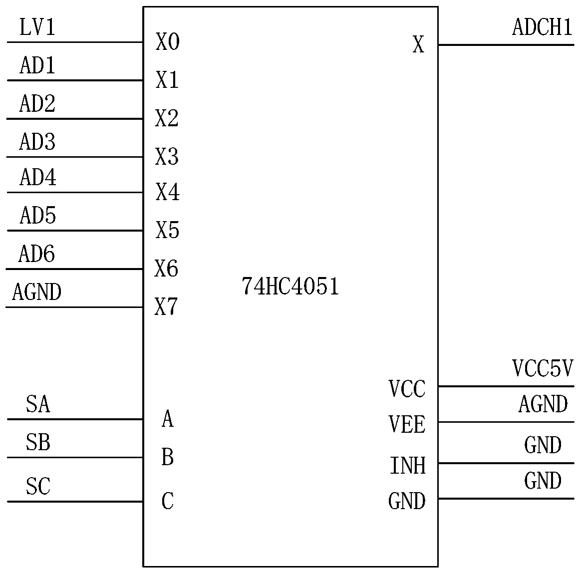
[0042] Such as figure 2 As shown, in view of the fast action of the ZK4 electro-pneumatic switch machine and the characteristics of the current value of the solenoid valve as a small signal DC, the current detection circuit at the sending end of the solenoid valve in this embodiment includes a perforated Hall current transformer, and according to the safety design principle, a perforated Hall current transformers are used to collect raw data, and the sampling locations are as follows Figure 8 As shown in the figure, pass the sending end line (i.e. the input side line) of the solenoid valve on the electropneumatic switch machine through the middle of the perforated Hall current transformer. The perforated Hall current transformer needs ±12V power supply, and the output of the perforated Hall current transformer After filtering and voltage stabilization, the analog multiplexer 74HC4051 is output to the AD port of the DSP, and the acquisition is completed by the DSP. The pin co...

Embodiment 2

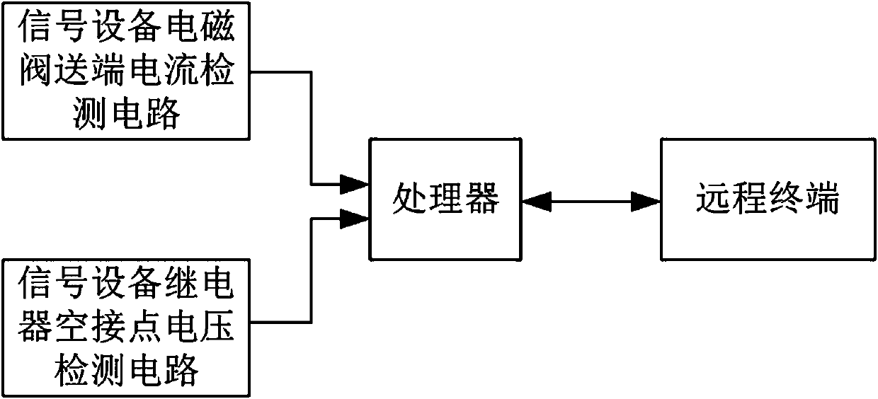
[0056] Such as Figure 9 As shown, the online monitoring system in this embodiment includes the voltage detection circuit at the sending end of the reducer, the current detection circuit of the solenoid valve at the sending end, and the relay state detection circuit. The detection circuits are all connected to the processing unit (that is, the electrical parameter acquisition system of the reducer), and the electrical parameter acquisition system of the reducer is connected to the remote terminal through the hump signal centralized monitoring system and the server in turn.

[0057] The current detection circuit at the sending end of the solenoid valve in this embodiment is the same as that in Embodiment 1, as figure 2 As shown, the perforated Hall current transformer is included, and according to the safety design principle, the perforated Hall current transformer is used for raw data collection, and the sending end line (ie, the input side line) of the solenoid valve on the ...


PUM


Abstract

The invention provides an online monitoring system for a hump signal device and an online monitoring method for a switch machine. A current detecting circuit of an electromagnetic valve transmitting terminal and a voltage detecting circuit of a relay empty idle contact are arranged to monitor a working current of a solenoid valve of a signal device and states of all relays continuously in real time; and then whether relevant operational indicators of the signal device meet the requirements is determined based on monitoring results to realize real-time monitoring of the signal device and carryout data recording and fault analysis conveniently. According to the invention, the ZK4 electro-pneumatic point machine is monitored to obtain a working current, a DCJ state, a DBJ state and an FBJ state of the solenoid valve; and a fault current, action time, a conversion direction, starting time and conversion time are determined based on the monitoring results; and real-time data information issent to a remote terminal and the data are displayed and stored.

Description

technical field [0001] The invention relates to the field of rail traffic monitoring, in particular to an on-line monitoring system for hump signal equipment and an on-line monitoring method for switch machines. Background technique [0002] With the gradual realization of hump automation in my country's marshalling stations, the daily maintenance of hump signal equipment has become increasingly prominent, and there are mainly the following outstanding problems: [0003] 1. At present, the real-time online monitoring of the electrical parameters of the signal equipment at Hump Station is in a vacant state, which leads to the hidden dangers of the early failure of the signal equipment that cannot be discovered in time, and when the signal equipment fails, there is a lack of electrical parameter record data before and after the failure, so as to locate the on-site fault, Troubleshooting causes a lot of trouble and seriously affects the efficiency of on-site troubleshooting. ...

Claims


Application Information

Patent Timeline
IPC IPC(8): G01R31/00G01R31/327G01R19/165G01R19/25B61K9/08
CPCB61K9/08G01R19/16528G01R19/25G01R31/00G01R31/327
Inventor 解豪杰刘伟云振东
Owner HENAN SPLENDOR SCI & TECH
Why Eureka
Try Eureka