Design method of variable cross-section three-dimensional internal contraction air inlet channel matched with curved cone projectile body

A design method and technology for air intakes, which are applied in computing, special data processing applications, instruments, etc., can solve the geometric complexity of the three-dimensional inwardly contracting air intake, and the lack of an integrated design method for the body and the three-dimensional inwardly contracting air intake. and other problems to achieve the effect of broadening the working Mach number range

Active Publication Date: 2019-09-06
NANCHANG HANGKONG UNIVERSITY
View PDF4 Cites 4 Cited by
  • Summary
  • Abstract
  • Description
  • Claims
  • Application Information

AI Technical Summary

Problems solved by technology

[0004] Due to its simple structure and high volume ratio, the curved cone body is more suitable for the development of hypersonic missile aircraft. However, due to the complexity of the geometric shape of the three-dimensional inner contraction inlet, the airframe and three-dimensional inner contraction have been lacking for a long time. The integrated design method of the intake port, especially the integrated design method of the three-dimensional retractable intake port for matching the curved cone body

Method used


Image

  • Design method of variable cross-section three-dimensional internal contraction air inlet channel matched with curved cone projectile body
  • Design method of variable cross-section three-dimensional internal contraction air inlet channel matched with curved cone projectile body
  • Design method of variable cross-section three-dimensional internal contraction air inlet channel matched with curved cone projectile body

Examples


Embodiment Construction

[0023] The preferred embodiments of the present invention will be described in detail below in conjunction with the accompanying drawings, so that the advantages and features of the present invention can be more easily understood by those skilled in the art, so as to define the protection scope of the present invention more clearly.

[0024] In this embodiment, it should be understood that the terms "middle", "upper", "lower", "top", "right side", "left end", "above", "back", "middle", etc. The indicated orientation or positional relationship is based on the orientation or positional relationship shown in the drawings, and is only for the convenience of describing the present invention, rather than indicating or implying that the referred device or element must have a specific orientation, be constructed and operated in a specific orientation , and therefore cannot be construed as a limitation of the present invention.

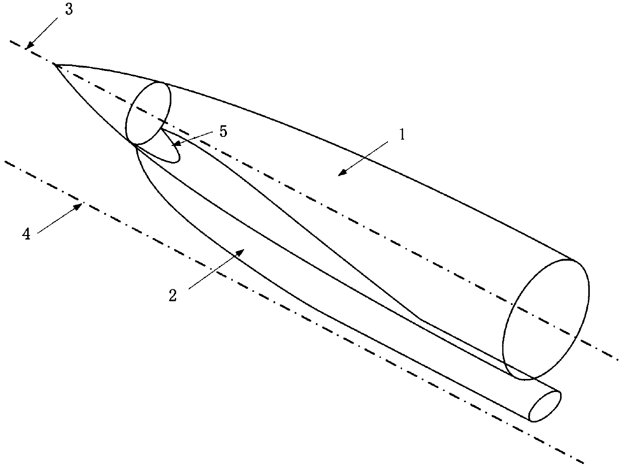
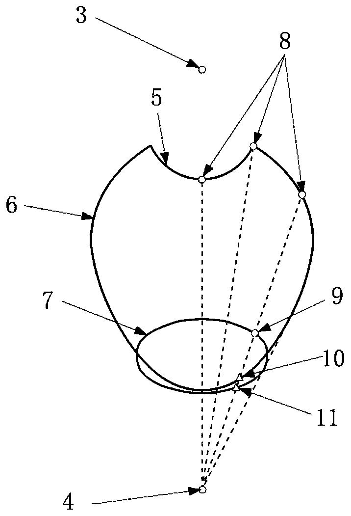
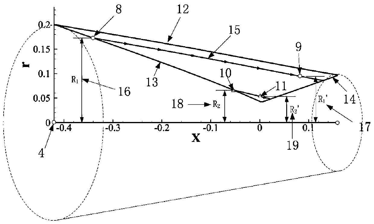
[0025]The design method of the variable cross-section th...


PUM


Abstract

The invention discloses a design method of a variable cross-section three-dimensional internal contraction air inlet channel matched with a curved cone projectile body, which comprises the curved coneprojectile body and the variable cross-section three-dimensional internal contraction air inlet channel and comprises the following steps: 1) designing the inlet shape of the variable cross-section three-dimensional internal contraction air inlet channel and the shoulder profile shape of the air inlet channel according to the geometric shape of the curved cone projectile body and the combustion chamber inlet shape requirement; 2) dispersing the inlet molded line of the air inlet channel and the shoulder molded line of the air inlet channel; 3) solving the axisymmetric basic flow field, and performing streamline tracking in the basic flow field according to the shape of the variable cross-section three-dimensional internal contraction air inlet to obtain a corresponding streamline; 4) cutting off the streamline according to the relative position of the inlet and outlet shapes of the variable cross-section three-dimensional internal contraction air inlet channel, and performing three-dimensional arrangement on the obtained streamline to obtain a variable cross-section three-dimensional internal contraction air inlet channel compression molded surface; and 5) on the basis of the variable-cross-section three-dimensional internal contraction air inlet channel compression molded surface, carrying out geometric construction on the variable-cross-section three-dimensional internal contraction air inlet channel matched with the curved cone projectile body.

Description

technical field [0001] The invention relates to the technical field of three-dimensional inwardly contracting air inlets, in particular to a design method for a variable-section three-dimensional inwardly contracting air inlet that matches a curved cone body. Background technique [0002] Close to the space vehicle is the strategic commanding height that various aviation powers in the world are competing for. World powers represented by the United States and Russia continue to carry out research on hypersonic vehicles. The key to realizing hypersonic flight is the air-breathing propulsion system, and the most important thing is the design of the hypersonic inlet. The air inlet is located at the front end of the propulsion system of the aircraft, and is directly connected to the precursor of the hypersonic aircraft, which plays the role of compressing the incoming flow and providing as much high-pressure and low-speed airflow as possible for the downstream. [0003] During ...

Claims


Application Information

Patent Timeline
Patent Type & Authority Applications(China)
IPC IPC(8): G06F17/50
CPCG06F30/17
Inventor 李怡庆江威孙通赵键
Owner NANCHANG HANGKONG UNIVERSITY
Why Eureka
Try Eureka