
Photon mapping optimization method, device and system based on polygon space division

A photon mapping and space division technology, applied in 3D image processing, 2D image generation, texture/color, etc., can solve the problem of no efficient scene division method and achieve good scalability

Active Publication Date: 2019-09-06
SHANDONG UNIV
View PDF5 Cites 2 Cited by
  • Summary
  • Abstract
  • Description
  • Claims
  • Application Information

AI Technical Summary

Problems solved by technology

[0005] However, the inventor found in the research and development process that there is no efficient scene division method in the current method that is suitable for scenes of large exhibition halls

Method used


Image

  • Photon mapping optimization method, device and system based on polygon space division
  • Photon mapping optimization method, device and system based on polygon space division
  • Photon mapping optimization method, device and system based on polygon space division

Examples


Embodiment 1

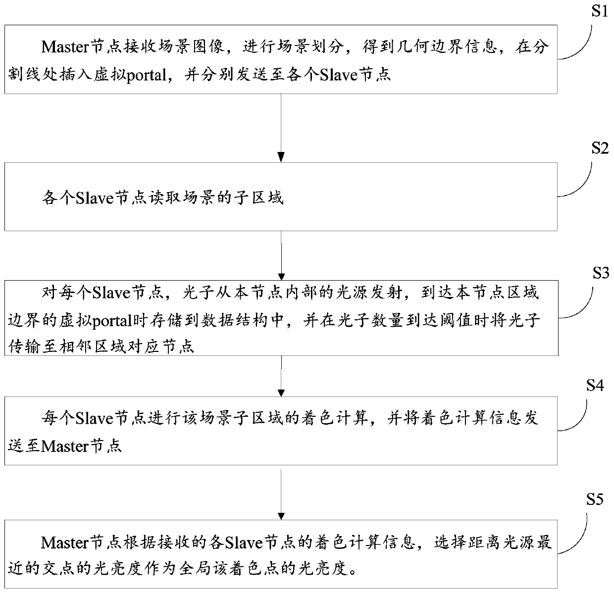
[0091] According to an aspect of one or more embodiments of the present disclosure, a method for optimizing photon mapping based on polygonal space partitioning is provided.

[0092] A photon mapping optimization method based on polygonal space division, the method comprising:

[0093] Scene division and loading phase:

[0094] The master node divides the outer contour of the scene into N parts according to the division method proposed in this paper, and sends the divided geometric boundary information to each slave node, and each slave node reads the sub-area of ​​the scene.

[0095] S1: The Master node receives the scene image, divides the scene, obtains the geometric boundary information, inserts a virtual portal at the dividing line, and sends it to each Slave node respectively;

[0096] S2: Each Slave node reads the sub-area of ​​the scene;

[0097] Photon emission stage:

[0098] S3: For each Slave node, photons are emitted from the light source inside the node and st...

Embodiment 2

[0147] According to an aspect of one or more embodiments of the present disclosure, a photon mapping optimization system based on polygonal space partitioning is provided.

[0148] A photon mapping optimization system based on polygonal space division, based on a kind of photon mapping optimization method based on polygonal space division in the embodiment, the system includes: a Master node and several Slave nodes connected thereto;

[0149] The Master node receives the scene image, divides the scene, obtains the geometric boundary information, inserts a virtual portal at the dividing line, and sends it to each Slave node respectively;

[0150] Each Slave node reads the sub-area of ​​the scene;

[0151] For each Slave node, photons are emitted from the light source inside the node, stored in the data structure when they reach the virtual portal at the border of the node area, and are transmitted to the corresponding node in the adjacent area when the number of photons reaches...

Embodiment 3

[0187] According to an aspect of one or more embodiments of the present disclosure, there is provided an electronic device.

[0188]An electronic device, which includes a processor and a computer-readable storage medium, the processor is used to implement instructions; the computer-readable storage medium is used to store a plurality of instructions, and the instructions are suitable for being loaded by the processor and executing the described one A photon mapping optimization method based on polygonal space partitioning.

[0189] These computer-executable instructions, when executed in a device, cause the device to perform the methods or processes described in accordance with various embodiments in the present disclosure.


PUM


Abstract

The invention discloses a photon mapping optimization method, device and system based on polygon space division, and the method comprises the steps: enabling a Master node to receive a scene image, carrying out the scene division, obtaining the geometric boundary information, enabling a virtual portal to be inserted at a division line, and enabling the virtual portal to be transmitted to each Slave node; enabling each Slave node to read a sub-region of the scene; for each Slave node, emitting photons from a light source in the node, are storing the photons in the data structure when the photons reaches the virtual port of the boundary of the region of the node, and transmiting the photons to corresponding nodes of an adjacent region when the number of the photons reaches a threshold value;enabling each Slave node to carry out coloring calculation on the scene sub-region and sending coloring calculation information to the Master node; and enabling the Master node to select the brightness of the intersection point closest to the light source as the brightness of the global coloring point according to the received coloring calculation information of each Slave node.

Description

technical field [0001] The disclosure belongs to the technical field of graphics realistic rendering, and relates to a photon mapping optimization method, device and system based on polygonal space division. Background technique [0002] The statements in this section merely provide background information related to the present disclosure and do not necessarily constitute prior art. [0003] In the fields of architecture, art, and especially digital cinema, there is an increasing demand for the scale and realism of mapped scenes. In order to generate photorealistic images, global illumination calculations are required to accurately simulate all lighting conditions in the scene. However, due to the large-scale spatial scene that needs to be rendered in the global illumination calculation, the large-scale illumination calculation tasks and large-scale scene data storage requirements brought by it bring new challenges to realistic rendering and visual effects simulation. Ther...

Claims


Application Information

Patent Timeline
Patent Type & Authority Applications(China)
IPC IPC(8): G06T11/00G06T15/55
CPCG06T11/001G06T15/55
Inventor 王璐王欣康春萌徐延宁孟祥旭马蕾蕾
Owner SHANDONG UNIV
Learn More