Panel design framework

A panel design, panel technology, applied in the direction of instruments, static indicators, etc., can solve the problem of widening the left and right borders

Inactive Publication Date: 2019-09-06
FUJIAN HUAJIACAI CO LTD
View PDF13 Cites 2 Cited by
  • Summary
  • Abstract
  • Description
  • Claims
  • Application Information

AI Technical Summary

Problems solved by technology

The advantage of this driving architecture is that it can improve the production yield and prolong the service life of the panel, but it will also make the left and right borders of the panel wider

Method used


Image

  • Panel design framework

Examples


Embodiment Construction

[0011] In order to explain in detail the technical content, structural features, achieved goals and effects of the technical solution, the following will be described in detail in conjunction with specific embodiments and accompanying drawings.

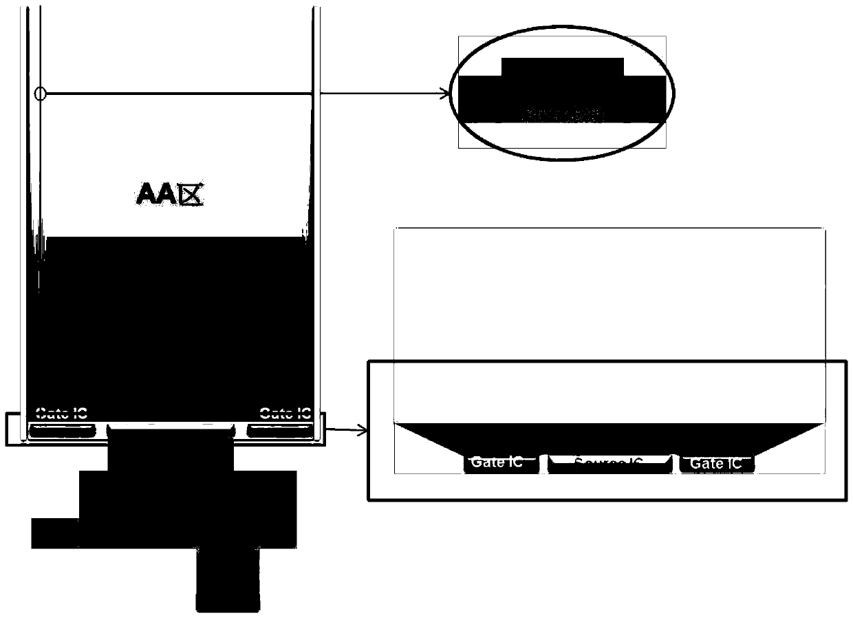
[0012] In the technical method to be explained in this article, in order to solve the problem of too wide border of the panel, such as figure 1 As shown, we provide a panel design framework, the source driver is arranged in the middle of the lower part of the display area of ​​the panel, the gate driver is arranged under the display area of ​​the panel, and is located on both sides of the source driver, the source The driver is connected to the source bus, the gate driver is connected to the gate bus, the source bus and the gate bus are arranged in the non-display area on the side of the panel, the connection between the source bus and the gate bus An OC (over coating insulating layer) layer is arranged between them, the source bus is...


PUM


Abstract

Provided is a panel design framework. A source electrode driver is arranged in the middle of the lower portion of a display area of a panel. The gate driver is arranged below the display area of the panel. The first transistor and the second transistor are located on two sides of the source driver. The source electrode driver is connected with the source electrode bus. The grid driver is connectedwith the grid bus. The source bus and the grid bus are arranged in a non-display area on the side of the panel, an OC layer is arranged between the source bus and the grid bus, the source bus is usedfor driving source signals of all display units on the panel, and the grid bus is used for driving grid signals of all the display units on the panel. Compared with the prior art, the technical scheme has the advantages that wiring can be carried out on the two sides of the panel at the same time, short circuit is prevented, and meanwhile the thickness of the display panel frame is reduced.

Description

technical field [0001] The invention relates to the field of display design, in particular to a panel design framework for reducing the frame width of a display screen. Background technique [0002] In the current design scheme, the display screen, as a production tool, is increasingly expected to have a larger display area and a smaller frame. Traditional discrete panel driver architecture, its architecture is Source IC with Gate IC. GateIC and Source IC are listed on the two sides and the bottom side of the AA area of ​​the panel. The advantage of this driving architecture is that it can improve the production yield and prolong the service life of the panel, but it also relatively widens the left and right borders of the panel. [0003] In today's panel market, the demand for panels with narrow bezels is constantly increasing, which greatly reduces the application of panel products with this discrete architecture, so a method is proposed to reduce the bezel width of the ...

Claims


Application Information

Patent Timeline
IPC IPC(8): G09G3/20
CPCG09G3/20
Inventor 不公告发明人
Owner FUJIAN HUAJIACAI CO LTD
Why Eureka
Try Eureka