Permanent magnet synchronous motor, robot and method for improving motor torque regulation function
A permanent magnet synchronous motor and permanent magnet technology, which is applied to synchronous motors with stationary armatures and rotating magnets, synchronous machine parts, magnetic circuits, etc., can solve the problems of inconvenient recalibration and high cost, and achieve improved gas Gap magnetic density, reduce the harmonic content of magnetic density, and improve the effect of harmonic noise
- Summary
- Abstract
- Description
- Claims
- Application Information
AI Technical Summary
Problems solved by technology
Method used
Image

Examples
Embodiment 1
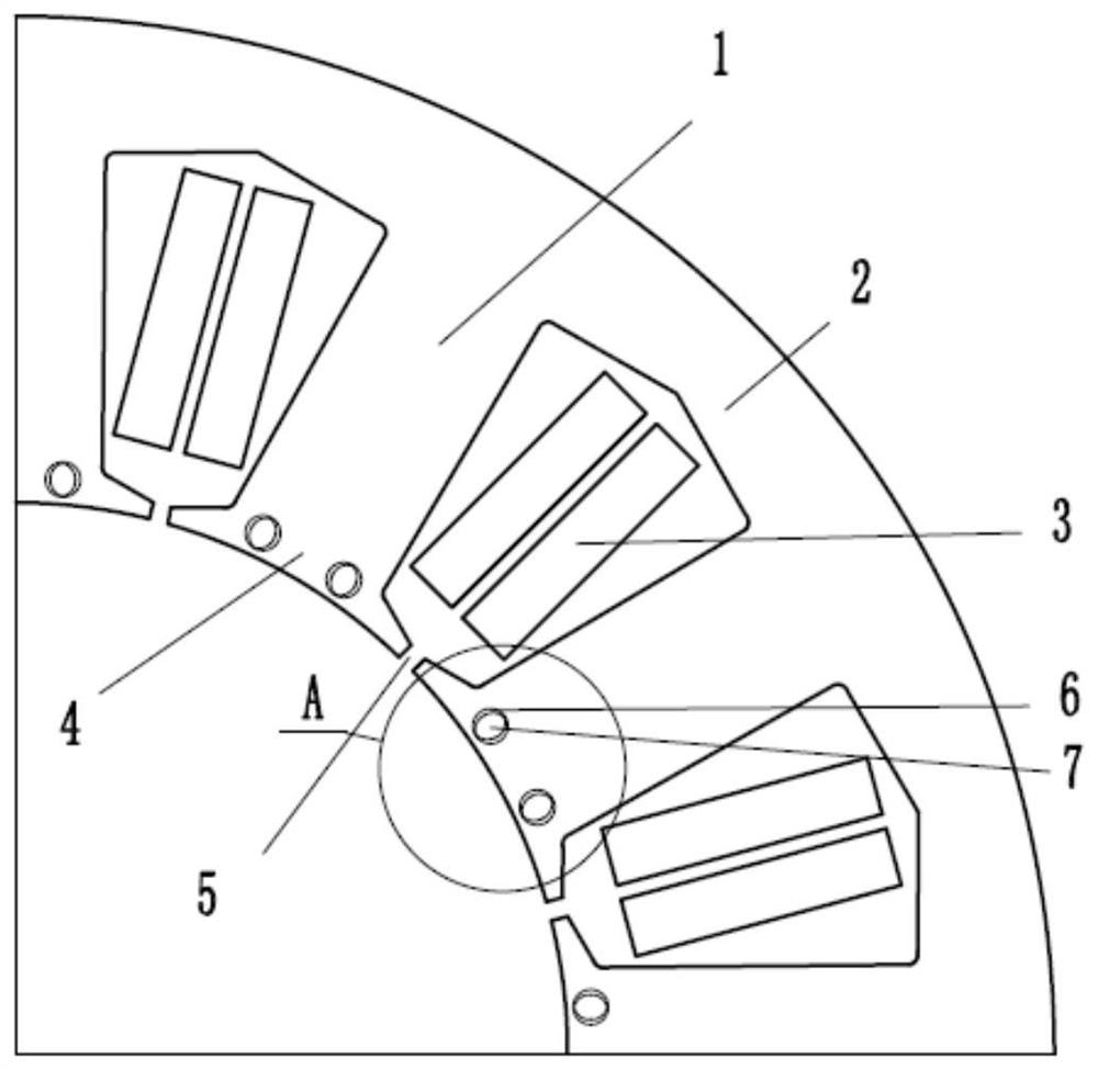
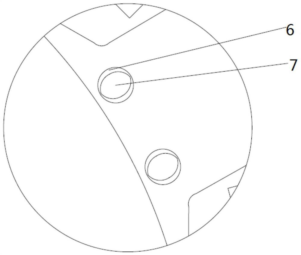
[0031] The invention provides a motor stator. like figure 1 As shown, the motor stator of the embodiment of the present invention includes stator cores 1, 2 and stator coils 3, the stator core includes stator teeth 1 and stator yoke 2, and the stator cores 1 and 2 are cylindrical or roughly cylindrical The structure has a plurality of stator slots 5 in the circumferential direction, and the stator slots 5 pass through the stator cores 1 and 2 in the axial direction, and the stator coil 3 is wound on the stator cores 1 and 2 through the stator slots 5. 1 and 2 are also provided with at least one auxiliary groove 6, and the magnetic generating component 7 is arranged in the auxiliary groove 6. Preferably, the magnet-generating component 7 can be adjusted to rotate or move relative to the auxiliary groove.
[0032] Further, such as figure 1 As shown, a boot 4 is formed at one end of the tooth part 1, and the auxiliary groove 6 is optimally opened on the boot part 4 of the stat...
Embodiment 2
[0042] The invention also provides a permanent magnet synchronous motor. It has the stator structure described in Embodiment 1. The application of the motor stator of the present invention on the motor is illustrated below through Embodiment 2.
[0043] The stator of the permanent magnet synchronous motor is usually powered by a frequency converter, and the conduction sequence and conduction rate of the armature windings of each phase of the stator are controlled according to the rotor position signal. The stator generates a circular rotating magnetic field through the three-phase symmetrical current, and the magnetic pulling force between the rotating magnetic field and the rotor magnetic poles pulls the rotor to rotate synchronously with the rotating magnetic field. Cogging torque is the torque generated by the interaction between the permanent magnet and the iron core when the winding of the permanent magnet motor is not energized. It is caused by the tangential component ...
Embodiment 4
[0062] The present invention also protects a method embodiment for improving the motor torque adjustment function, which makes the motor stator have the above-mentioned motor stator structure.
[0063] like Figure 5 The current motor shown also has a stator core and a stator coil. The stator core also includes a stator tooth portion 101 and a stator yoke portion 102. The stator tooth portion 101 is circumferentially provided with a plurality of stator slots 105, and the stator slots 105 Through the axial direction of the stator core, the stator coil 103 is wound on the stator core 101 through the stator slot 105 . This patent proposal retains these structural advantages of the current motor, improves its stator structure, and sets an auxiliary groove magnetic generating part at the shoe part of its teeth, so that its magnetic field can be adjusted. The magnetic generating part is preferably a magnetically conductive steel rod, the shape of the auxiliary groove is designed to...
PUM
 Abstract
Description
Claims
Application Information
 - R&D
- Intellectual Property
- Life Sciences
- Materials
- Tech Scout
- Unparalleled Data Quality
- Higher Quality Content
- 60% Fewer Hallucinations
Browse by: Latest US Patents, China's latest patents, Technical Efficacy Thesaurus, Application Domain, Technology Topic, Popular Technical Reports.
© 2025 PatSnap. All rights reserved.Legal|Privacy policy|Modern Slavery Act Transparency Statement|Sitemap|About US| Contact US: help@patsnap.com