Test device and test method for live oil pipe hydraulic cylinder with built-in piston rod

A test device and live oil pipe technology, applied in the field of hydraulic cylinders, can solve the problems of high cost of test benches, unaffordable enterprises, large installed flow rate and installed power of test benches, etc., and achieve a simple and reliable structure, compact structure, and strong bearing capacity. Effect

Pending Publication Date: 2022-08-09
XCMG HYDRAULICS CO LTD
View PDF1 Cites 0 Cited by
  • Summary
  • Abstract
  • Description
  • Claims
  • Application Information

AI Technical Summary

Problems solved by technology

[0010] It can be seen that for the live oil pipes used in this type of large-bore and long-stroke hydraulic cylinders, if a rapid pulse test is required, the installed flow and installed power of the test bench are huge, and the cost of the test bench is extremely high, which cannot be afforded by ordinary companies.

Method used


Image

  • Test device and test method for live oil pipe hydraulic cylinder with built-in piston rod
  • Test device and test method for live oil pipe hydraulic cylinder with built-in piston rod
  • Test device and test method for live oil pipe hydraulic cylinder with built-in piston rod

Examples


Embodiment 1

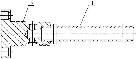
[0040] Combine Figure 1 to Figure 4 It shows, a live oil tube hydraulic cylinder test device with a built -in piston rod, oil pipe seat 3 and active oil pipe 4 through welding connection, and the radius of the live oil pipe 4 is arranged with M16 × 1.5 oil port to the trial activity to try the test activity. Oil pipe 4 tests.

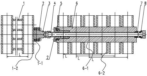
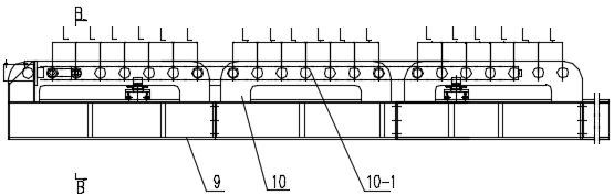
[0041] The test tables include rack 9, and the side plate 10 with symmetrical layout on the rack 9. There are multiple sets of relative sales holes 10-1 on the side board 10. Most pairs of the spacing between the tail positioning sleeve 1-2, the distance between the front position 6-2 and the spacing between 10-1 of the 10-1 of the multi-group side plate 10-1.

[0042] The main body of the rear connection device 1 is in the shaped shape, which includes the connection seat 1-1, the oil pipe seat 3 and the connection seat 1-1 to fix the connection through the screw 2. Connect 1-1 on the left side of two pairs of more than two panels 10-1 on the tail positioni...

Embodiment 2

[0047] On the basis of the above -mentioned Examples, a daily hydraulic cylinder test method, including the following steps:

[0048] A. Fix the oil pipeline 3 on the connection seat 1-1 connected to the tail connection device; the tail positioning sleeve 1-2 of the tail connection device 1 through the axis cover 11 and the sales axis 12 and the side board 10 on the test table 10 Sales holes 10-1 connection; two pairs of tail positioning sleeve 1-2 connection guarantees that there is no rotation of the live oil tube due to hinge rotation;

[0049] B. Put the live oil pipe 4 in the main body 6-1 center hole of the guide cover 5 and the front connection device 6; 10-1 connection of the side plate 10-1 on the test table;

[0050] C. Put the oil port and joint 8 on the oil port 3 into the hydraulic system; to inject hydraulic oil into the live oil pipe 4 through the hydraulic system, the intermediate radial direction of the actual oil pipe 4 will generate a certain amount. Disposal in...


PUM

PropertyMeasurementUnit
Outer diameteraaaaaaaaaa
Wall thicknessaaaaaaaaaa

Abstract

The invention discloses a live oil pipe hydraulic cylinder test device with a built-in piston rod simulation environment and a test method. The test bench comprises a rack, and symmetrically arranged side plates are fixed on the rack. A plurality of groups of opposite pin holes are formed in the side plates; the tail connecting device comprises a connecting seat, and the oil pipe seat is fixedly connected with the connecting seat; a tail positioning sleeve is fixed on the left side of the connecting seat; the front connecting device comprises a main body, and the movable oil pipe penetrates through a center hole of the main body; a guide sleeve is mounted at the left end of the body center hole; a front positioning sleeve is fixed on the peripheral surface of the main body; a core pipe is fixed to the right end of the center hole of the body and connected with a connector. The device is simple and reliable in structure, compact in structure and high in bearing capacity; the fixing mode of the front and rear ends of the live oil pipe meets the actual working condition requirements, the installation distance is convenient to adjust, and the live oil pipe offset under different working conditions can be simulated and tested; the method for testing the lap joint length of the inner hole and the end face of the live oil pipe under the stress condition is reliable in test data and high in practicability.

Description

Technical field [0001] The invention involves the field of hydraulic cylinder technology, which is specifically a activated hydraulic cylinder testing device and test method with a live oil pipe hydraulic cylinder with a built -in piston simulation environment. Background technique [0002] Reactor pipe: Encenting inside the piston rod, in the telescopic oil cylinder with a multi -core tube, the end is fixed with the bottom of the cylinder through the screw, a kind of oil pipe that can be moved to the second cavity with oil. [0003] At present, due to the development trend of car cranes and multi -knitting arms on the ground, in order to increase the load weight and expand the range of laid -load, the crane tending arm uses the extended telescopic arm structure, resulting in a telescopic oil cylinder that drives the extension of the thumbnail and retracting back and forth back and forth. The length of the internal oil pipes is getting longer and longer. When the retractable arm ...

Claims


Application Information

Patent Timeline
IPC IPC(8): F15B15/14F15B19/00
CPCF15B15/14F15B19/00
Inventor 陈向兵郑圆圆翟新颖彭亮金全明姚德川
Owner XCMG HYDRAULICS CO LTD
Why Eureka
Try Eureka