Numerical control tool rest static rigidity testing device and method

A testing device and static stiffness technology, applied in the direction of measuring devices, elastic testing, machine/structural parts testing, etc., can solve problems such as unclear loading point positions, complex loading device structures, and incomplete rigidity testing functions, etc., to achieve Simple and compact effect with high repeatability and reliability

Pending Publication Date: 2022-06-07
NANJING UNIV OF SCI & TECH
View PDF3 Cites 0 Cited by
  • Summary
  • Abstract
  • Description
  • Claims
  • Application Information

AI Technical Summary

Problems solved by technology

[0004] The technical problem to be solved by the present invention is that the position of the force loading point of the CNC horizontal servo tool holder is not clear, does not conform to the actual working conditions of the lathe, the structure of the loading device is complex, and the rigidity test function is not comprehensive.

Method used


Image

  • Numerical control tool rest static rigidity testing device and method
  • Numerical control tool rest static rigidity testing device and method
  • Numerical control tool rest static rigidity testing device and method

Examples


Embodiment 1

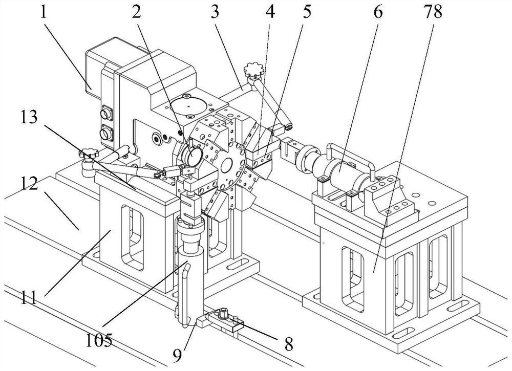
[0042] combine figure 1 , A numerical control tool rest static stiffness test device of this example includes a numerical control tool rest test bench, a force loading device, a deformation measurement device and a horizontal iron 12, a control system, and a data acquisition system. The numerical control tool rest test platform and the force loading system The device is fixedly installed on the floor iron 12, and the deformation measurement device is installed on the CNC tool rest test table; the control system is used to control the rotation of the tool rest to test the rigidity of the tool rest at different tool positions, and the data acquisition system is used for Upload the test data of the force loading device and the deformation measuring device to the industrial computer.

[0043] The CNC tool rest test bench includes a tested tool rest 1 , a tool rest adapter plate 13 , a test bench 11 , a simulated dummy knife 4 and a clamping block 5 ; the test bench 11 is fixedly i...

Embodiment 2

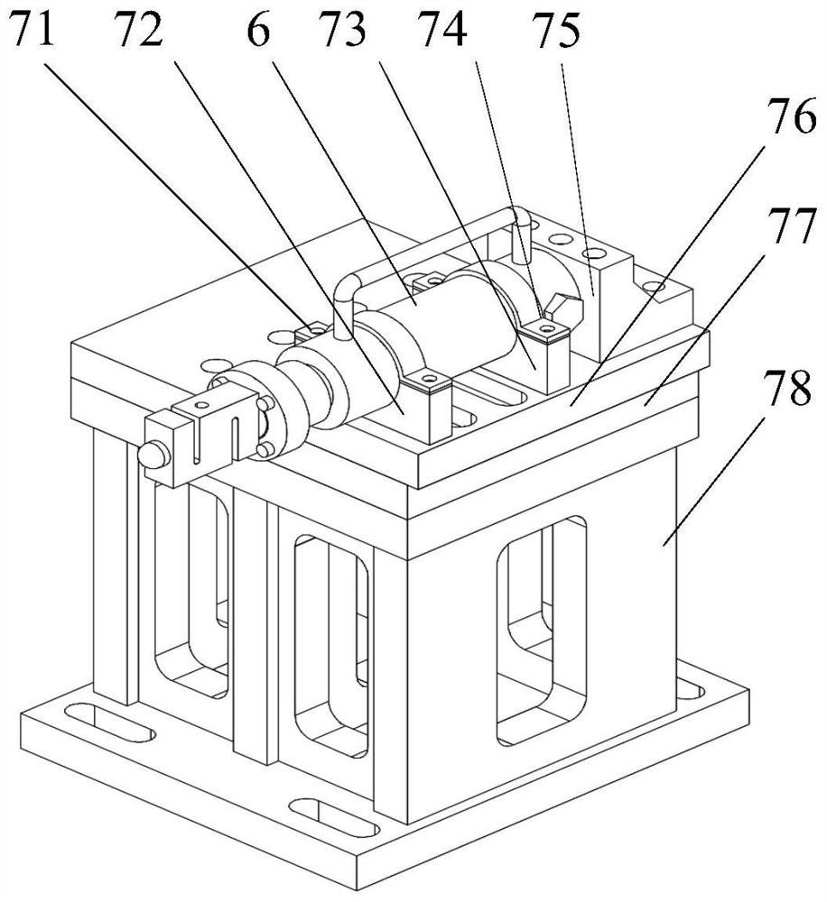
[0063] combine Image 6 The difference between Embodiment 2 and Embodiment 1 is that, on the basis of Embodiment 1, the axial position of the axial loading device is adjusted to be located in the reverse direction of the axis of the tool holder, and the shaft reverse deformation measuring device 14 and the bracket 15 are added. 15. The bolts are fixed on the floor iron 12, and the shaft reverse deformation measuring device 14 is adsorbed on the bracket 15. Other installation requirements and testing methods are the same as those of the first embodiment, and the shaft reverse static stiffness of the tool holder can be measured.


PUM


Abstract

The invention discloses a numerical control tool rest static rigidity testing device and method, and belongs to the field of comprehensive performance detection of functional parts of numerical control machine tools. The numerical control knife rest static rigidity testing device comprises a numerical control knife rest testing table, a force loading device, a deformation measuring device, horizontal iron, a control system and a data acquisition system. The numerical control knife rest test bench and the force loading device are fixedly installed on the horizontal iron, the deformation measuring device is installed on the numerical control knife rest test bench, the control system is used for controlling the knife rest to rotate so as to test the knife rest rigidity of different knife positions, and the data acquisition system is used for uploading test data of the force loading device and the deformation measuring device to the industrial personal computer. The testing device is simple and compact in structure, large in loading force range and capable of supporting static rigidity testing and maximum bearing capacity testing of numerical control tool rests of various models, multiple directions and various stations; the testing method defines the position of a force loading action point, the actual working condition requirement of the lathe is better met, and the measuring result is high in repeatability and credibility.

Description

technical field [0001] The invention relates to a static stiffness testing device and method, in particular to a static stiffness testing device and method of a numerically controlled tool rest, belonging to the field of comprehensive performance detection of functional components of numerically controlled machine tools. Background technique [0002] As domestic machine tool users urgently need "high-end, sophisticated" machine tool equipment to enhance their core competitiveness in recent years, their requirements for machine tool product performance have gradually increased. The static stiffness of the CNC tool holder is defined as the ability of the tool holder to resist static deformation at the position of the tool tip. As the core functional component of the CNC lathe, the CNC tool holder directly participates in the cutting process of the parts. Therefore, the static stiffness performance of the tool holder directly affects the quality of the machined parts, and has a...

Claims


Application Information

Patent Timeline
Patent Type & Authority Applications(China)
IPC IPC(8): G01M5/00
CPCG01M5/005Y02P90/02
Inventor 汪满新杨益诚韩军冯虎田欧屹
Owner NANJING UNIV OF SCI & TECH
Why Eureka
Try Eureka