Anesthetic mask

An anesthesia mask and mask technology, which is applied to respiratory masks, medical devices, other medical devices, etc., can solve the problems of patient discomfort, troublesome operation, and workload of doctors, so as to reduce workload, avoid oxygen waste, and have strong practicability. Effect

Active Publication Date: 2019-09-10
XINXIANG YATAI MEDICAL PROD CO LTD
View PDF5 Cites 10 Cited by
  • Summary
  • Abstract
  • Description
  • Claims
  • Application Information

AI Technical Summary

Problems solved by technology

[0002] The anesthesia mask is a medical emergency equipment used in conjunction with an anesthesia machine and a ventilator. It implements anesthesia gas delivery for patients to inhale anesthesia gas. pain, so that the operation can be carried out smoothly. At present, clinically, the anesthesia mask used for general anesthesia induction and first aid recovery includes a mask body, an air inlet at the upper end of the mask body, and a ring-shaped airtight mask airbag at the lower end of the mask body. , usually after the gas anesthesia is completed on the patient, it is difficult for the patient to breathe spontaneously due to general anesthesia. At this time, the patient must be supplied with oxygen. Usually, the doctor takes off the anesthesia mask and replaces the patient with oxygen Masks or nasal cannula for patients to continue to deliver oxygen to patients, but this operation is cumbersome and brings unnecessary workload to doctors;
[0003] Oxygen supply by oxygen masks can effectively and quickly increase the saturation of blood samples and improve the hypoxic state of patients. It is mostly used for coma and severe patients. Therefore, when patients undergo general anesthesia, most of them will use oxygen masks for oxygen supply, but oxygen Oxygen is supplied to the patient in th

Method used


Image

  • Anesthetic mask
  • Anesthetic mask
  • Anesthetic mask

Examples


Embodiment 1

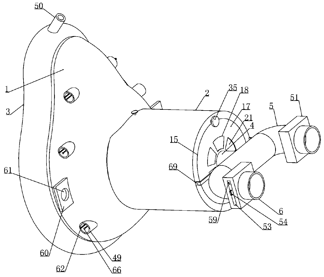
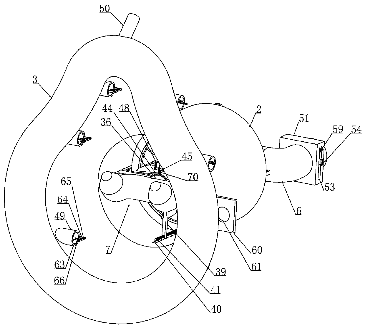
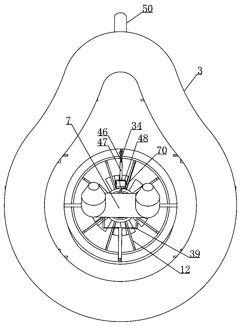
[0042] Embodiment 1, an anesthesia mask, including a mask 1, the upper end of the mask 1 is connected with an air intake pipe 2 and the bottom of the mask 1 is connected with an air cushion 3, it is characterized in that the end of the air intake pipe 2 away from the mask 1 is spaced with a fixed On the main air pipe 4 on the air intake pipe 2, the end of the air intake pipe 2 away from the mask 1 is rotated and installed with an exhaust valve that is rotatably matched with the main air pipe 4, and the main air pipe 4 passes through the exhaust valve and one end is connected with an anesthesia pipe 5 respectively and oxygen tube 6, the mask 1 is provided with a nasal cannula 7 and the nasal cannula 7 is connected with a hose 8 that is horizontally slidably connected in the intake pipe 2, and the other end of the hose 8 is rotatably connected to a The cylinder 9 is arranged on the axis, and the first ring 10 is arranged coaxially with the cylinder 9 in the intake pipe 2, and the...

Embodiment 2

[0048] Embodiment 2, on the basis of Embodiment 1, the first round hole 15 is provided on the end of the air intake pipe 2 away from the face mask 1 and the inner wall of the first round hole 15 is provided with a circular slideway 16, and the exhaust valve includes a rotating installation The circular plate 17 in the circular slideway 16 and the central position of the circular plate 17 is provided with a second circular hole 70 which is rotatably matched with the main air pipe 4, and a plurality of fan-shaped holes 18 are provided on the circular plate 17 around the second circular hole at intervals. The end of the fan-shaped hole 18 away from the second round hole is provided with a housing cavity 19, and the bottom wall of the housing cavity 19 is provided with a first rectangular slideway 20 along the diameter direction of the circular plate 17, and a fan-shaped plate is slidably connected to the first rectangular slideway 20. 21 , the sector plate 21 is connected to the f...

Embodiment 3

[0051] Embodiment 3, on the basis of Embodiment 1, the cylinder 9 includes a circular tube 23 coaxial with the main air pipe 4 and an annular plate 24 coaxial with the circular tube 23 is integrally provided on the outer wall of the circular tube 23 A number of fan blades 12 are installed between the first ring 10 and the annular plate 24 through the first shaft 25, and the first shaft 25 close to one end of the circular tube 23 passes through the annular plate 24 and is placed in the circular tube 23. The first shaft 25 passing through the annular plate 24 is placed in the circular tube 23 and one end is connected with the first transmission device. The other end of the circular tube 23 is fixedly connected with the annular slideway 26 with the center of the shaft. The hose 8 is close to the circular slideway. One side of the road 26 is integrally connected with a first hard pipe 27 and the first hard pipe 27 is rotatably installed in the annular slideway 26. The side of the m...


PUM


Abstract

The invention relates to an anesthetic mask. By adopting the anesthetic mask, the problems are effectively solved that by adopting current anesthetic masks, anesthesia and oxygen supply cannot be compatible, and vapor inside the anesthetic mask cannot be well removed. According to the technical scheme, the anesthetic mask includes a mask body, an air inlet pipe is communicated with the upper end of the mask body, exhaust airing channels are arranged at the two longitudinal sides of the mask body respectively, a main air pipe is coaxially arranged inside the air inlet pipe and is communicated with an anesthetic catheter and an oxygen supply catheter separately, a nasal catheter is arranged inside the mask body, a soft pipe communicated with the nasal catheter is arranged inside the air inlet pipe, and the other end of the soft pipe is connected with a dehumidification device. When the content of the vapor inside the anesthetic mask is too high, the soft pipe is communicated with the main air pipe, at the same time, the dehumidification device discharges the vapor inside the anesthetic mask, external air continuously enters the mask body through the exhaust airing channels, and therefore, the effect of making air with high humidity inside the mask body discharged from the mask body; the anesthetic mask is high in flexibility and practicability and convenient to operate.

Description

technical field [0001] The invention belongs to the technical field of medical equipment, and in particular relates to an anesthesia mask, which is used for preoperative anesthesia of surgical patients in medical clinics. Background technique [0002] The anesthesia mask is a medical emergency equipment used in conjunction with an anesthesia machine and a ventilator. It implements anesthesia gas delivery for patients to inhale anesthesia gas. pain, so that the operation can be carried out smoothly. At present, clinically, the anesthesia mask used for general anesthesia induction and first aid recovery includes a mask body, an air inlet at the upper end of the mask body, and a ring-shaped airtight mask airbag at the lower end of the mask body. , usually after the gas anesthesia is completed on the patient, it is difficult for the patient to breathe spontaneously due to general anesthesia. At this time, the patient must be supplied with oxygen. Usually, the doctor takes off th...

Claims


Application Information

Patent Timeline
IPC IPC(8): A61M16/06A61M16/10A61M16/12A61M16/00A61M16/01A61M16/20
CPCA61M16/0605A61M16/0672A61M16/104A61M16/125A61M16/0054A61M16/01A61M16/20A61M16/06A61M16/0833A61M16/208A61M2205/583A61M16/161A61M2205/50A61M2205/18A61M16/0051A61M2205/103A61M16/0066A61M16/0009A61M2202/062A61M2202/0241A61M2202/0208A61M16/205A61M2205/3365A61M16/0683A61M16/024A61M2202/0007
Inventor 范丽娜刘红霞刘安成王小玲
Owner XINXIANG YATAI MEDICAL PROD CO LTD
Why Eureka
Try Eureka