Eureka AIR delivers breakthrough ideas for toughest innovation challenges, trusted by R&D personnel around the world.

Gearbox cavity die moving die

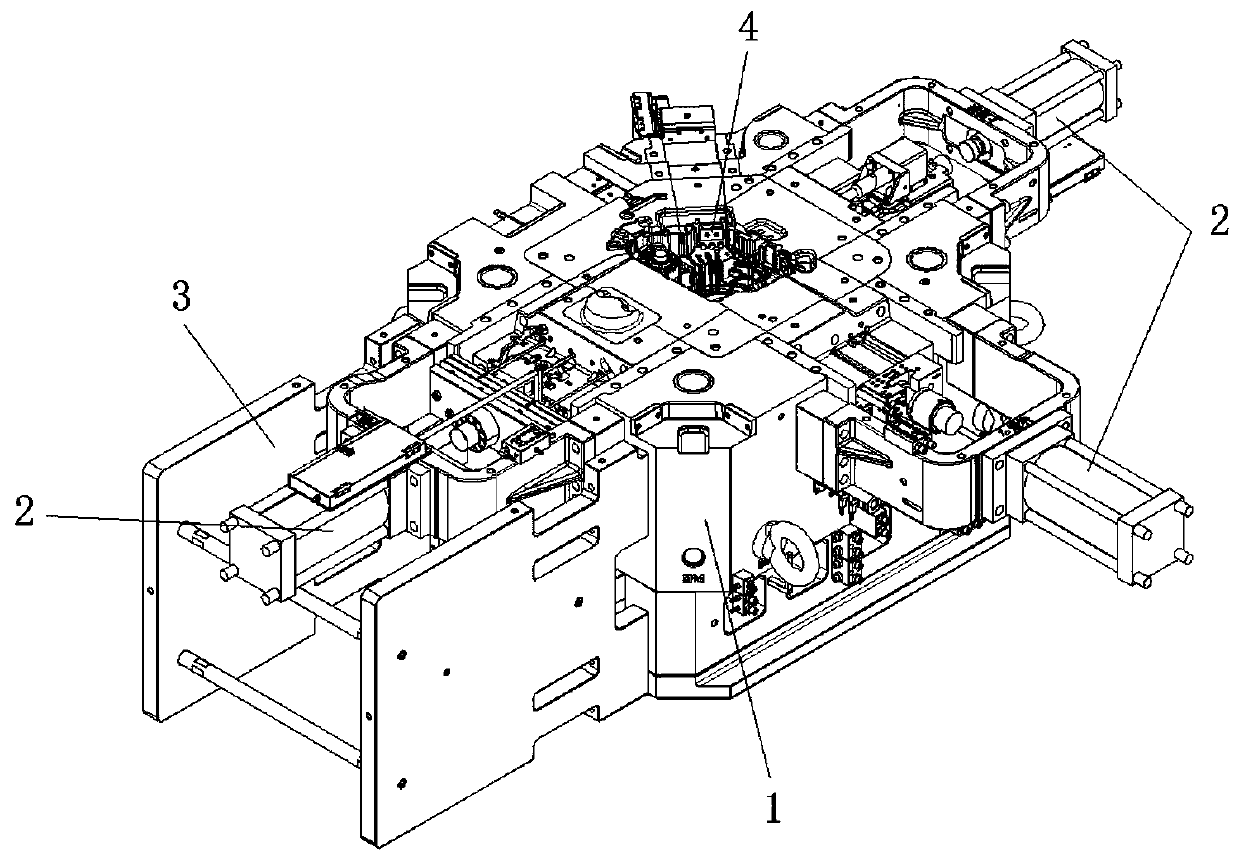
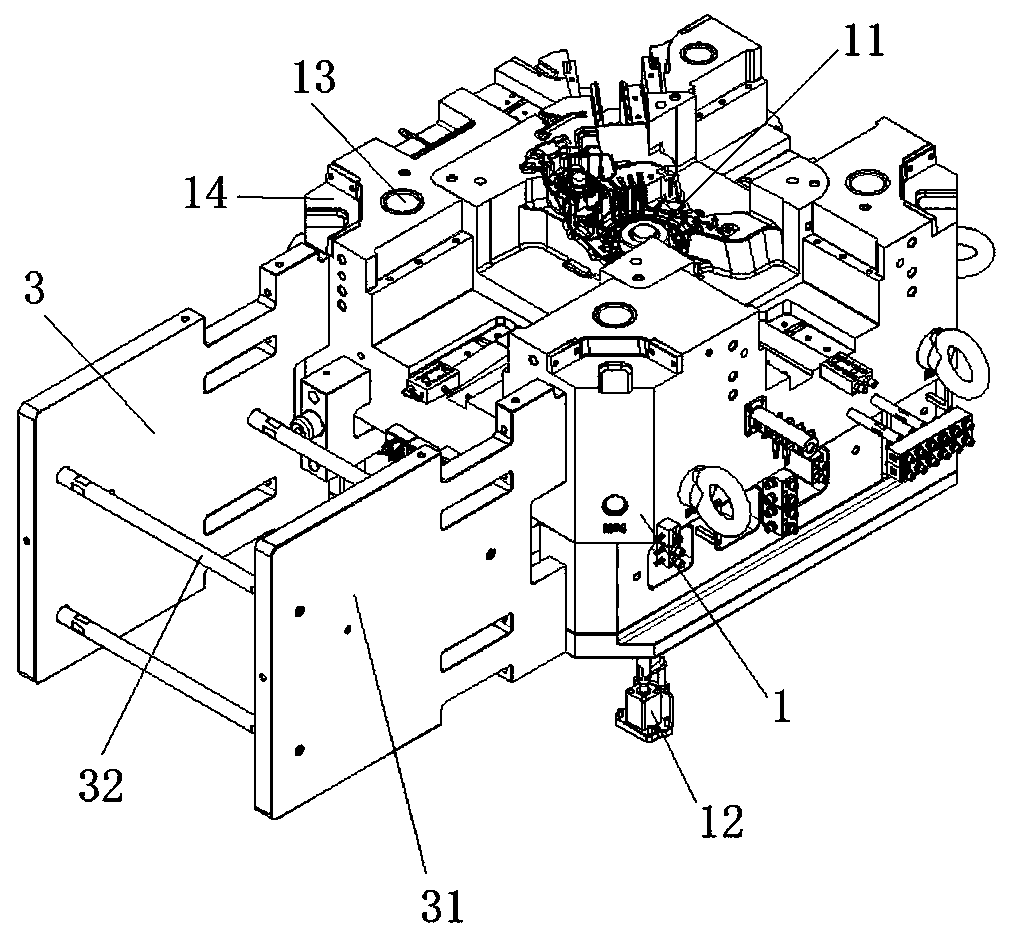
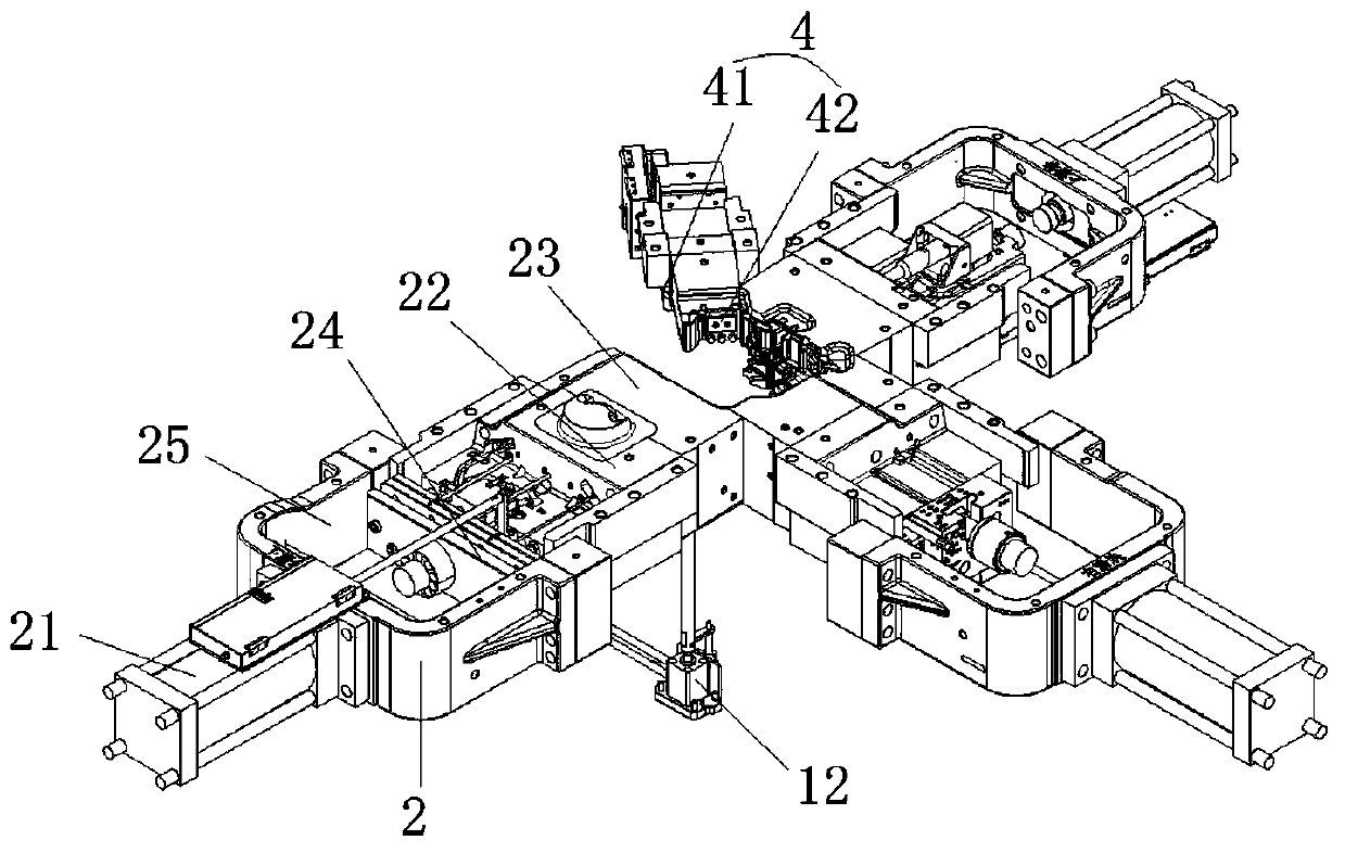
A gearbox and movable mold technology, applied in the field of gearbox cavity mold movable mold, can solve the problems affecting the casting accuracy and quality of gearboxes, inaccurate mold clamping, etc., and achieve simple structure, accurate mold clamping, and high casting accuracy. Effect

Pending Publication Date: 2019-09-10
GUANGZHOU DIE & MOLD MFG
View PDF0 Cites 2 Cited by
  • Summary
  • Abstract
  • Description
  • Claims
  • Application Information

AI Technical Summary

Problems solved by technology

The prior art gearbox cavity molds generally require die-casting machines to close and open the molds. However, due to the large movements of the die-casting machines, inaccurate mold closing may occur, which affects the casting accuracy and quality of the gearbox.

Method used


Image

  • Gearbox cavity die moving die
  • Gearbox cavity die moving die
  • Gearbox cavity die moving die

Examples


Embodiment Construction

[0023] The directional terms such as up, down, left, right, front, back, front, back, top, and bottom that are mentioned or may be mentioned in this specification are defined relative to the structures shown in the drawings, and they are relative concept. Therefore, it is possible to make corresponding changes according to its different positions and different usage states. Accordingly, these or other directional terms should not be construed as limiting terms.

[0024] The implementations described in the following exemplary examples do not represent all implementations consistent with the present disclosure. Rather, they are merely examples of approaches consistent with aspects of the disclosure as recited in the appended claims.

[0025] The terminology used in the present disclosure is for the purpose of describing particular embodiments only, and is not intended to limit the present disclosure. As used in this disclosure and the appended claims, the singular forms "a",...


PUM


Abstract

The invention discloses a gearbox cavity die moving die. The gearbox cavity die moving die comprises a moving die base and multiple sliding mechanisms. A first die core matched with the shape of a gearbox is arranged in the middle of the moving die base. A moving die extrusion oil cylinder is arranged on one side of the moving die base. A piston rod of the moving die extrusion oil cylinder vertically faces the moving die base and can be connected with the first die core in an abutting manner. The multiple sliding mechanisms are arranged along the periphery of the moving die base. Each of the multiple sliding mechanisms comprises a sliding cylinder and a sliding die. A piston rod of each sliding cylinder is connected with a corresponding sliding die. Pistons rods of the sliding cylinders vertically face the first die core. A second die core matched with the shape of the gearbox is arranged on a side edge of each sliding die. According to the gearbox cavity die moving die, the moving dieextrusion oil cylinder is arranged on one side of the moving die base, and the multiple sliding mechanisms are arranged; and when a gearbox is cast, accurate location can be conducted on the first die core and the second die cores so that die closing is accurate, and thus the casting precision and quality of the gearbox are improved.

Description

technical field [0001] The invention relates to the field of automobile processing and manufacturing equipment, in particular to a movable mold of a gearbox cavity mold. Background technique [0002] The gearbox is a very important part of the vehicle. It can change the transmission ratio and expand the torque and speed of the driving wheels. Gearboxes are usually cast in cavity molds. The prior art gearbox cavity molds generally require die-casting machines to close and open the molds. However, due to the large movements of the die-casting machines, inaccurate mold closing may occur, which affects the casting accuracy and quality of the gearbox. Contents of the invention [0003] Based on this, the purpose of the present invention is to provide a transmission cavity mold movable mold with the characteristics of simple structure, precise mold clamping, and high casting precision. [0004] The movable mold of the gearbox cavity mold of the present invention comprises a mo...

Claims


Application Information

Patent Timeline
Patent Type & Authority Applications(China)
IPC IPC(8): B22D17/22B22D17/26
CPCB22D17/22B22D17/266
Inventor 岑伟明黄志敏陈珊娜
Owner GUANGZHOU DIE & MOLD MFG
Why Eureka
Eureka Blog
Learn More