Rear suspension pull rod structure for connecting power assembly with front sub frame

A front subframe and powertrain technology, which is applied to the power plant, substructure, vehicle components, etc., can solve the problem of insufficient life to meet the design requirements, and achieve the effect of optimizing noise and improving life.

Active Publication Date: 2019-09-10
ZHEJIANG LEAPMOTOR TECH CO LTD
View PDF6 Cites 3 Cited by
  • Summary
  • Abstract
  • Description
  • Claims
  • Application Information

AI Technical Summary

Problems solved by technology

[0004] The invention overcomes the problem that the current rear suspension rod cannot adapt to the higher and higher torque of the current automobile action assembly, resulting in insufficient service life to meet the design requirements, and

Method used


Image

  • Rear suspension pull rod structure for connecting power assembly with front sub frame
  • Rear suspension pull rod structure for connecting power assembly with front sub frame
  • Rear suspension pull rod structure for connecting power assembly with front sub frame

Examples


Embodiment 1

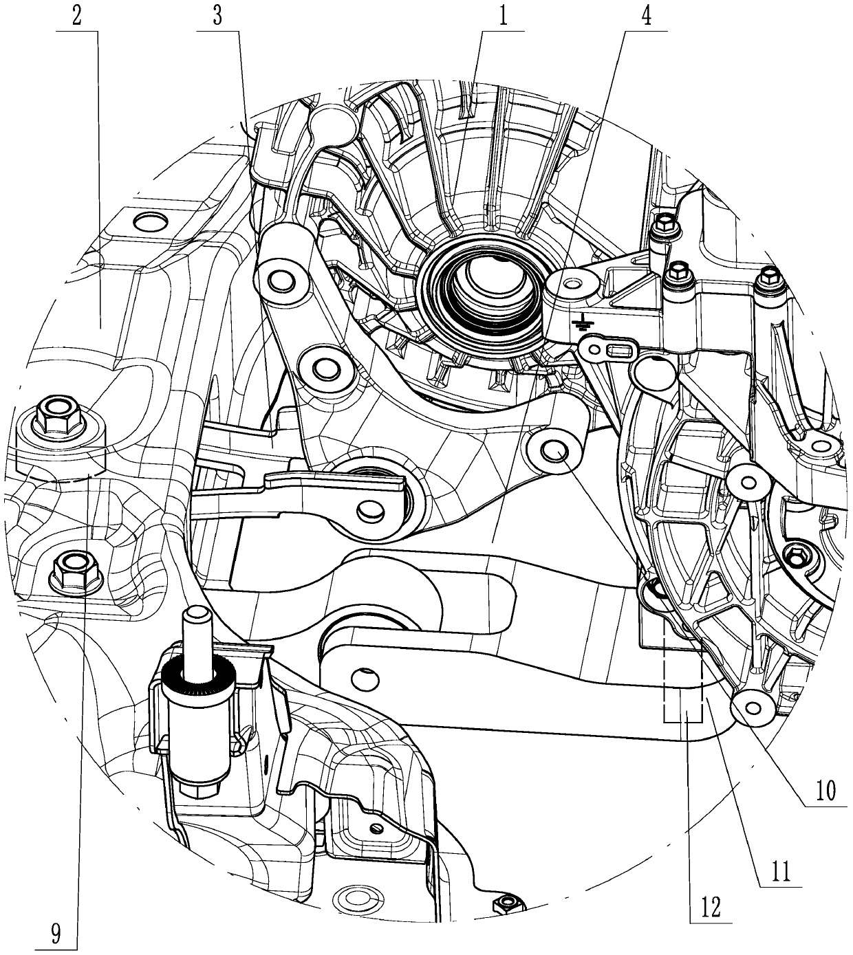
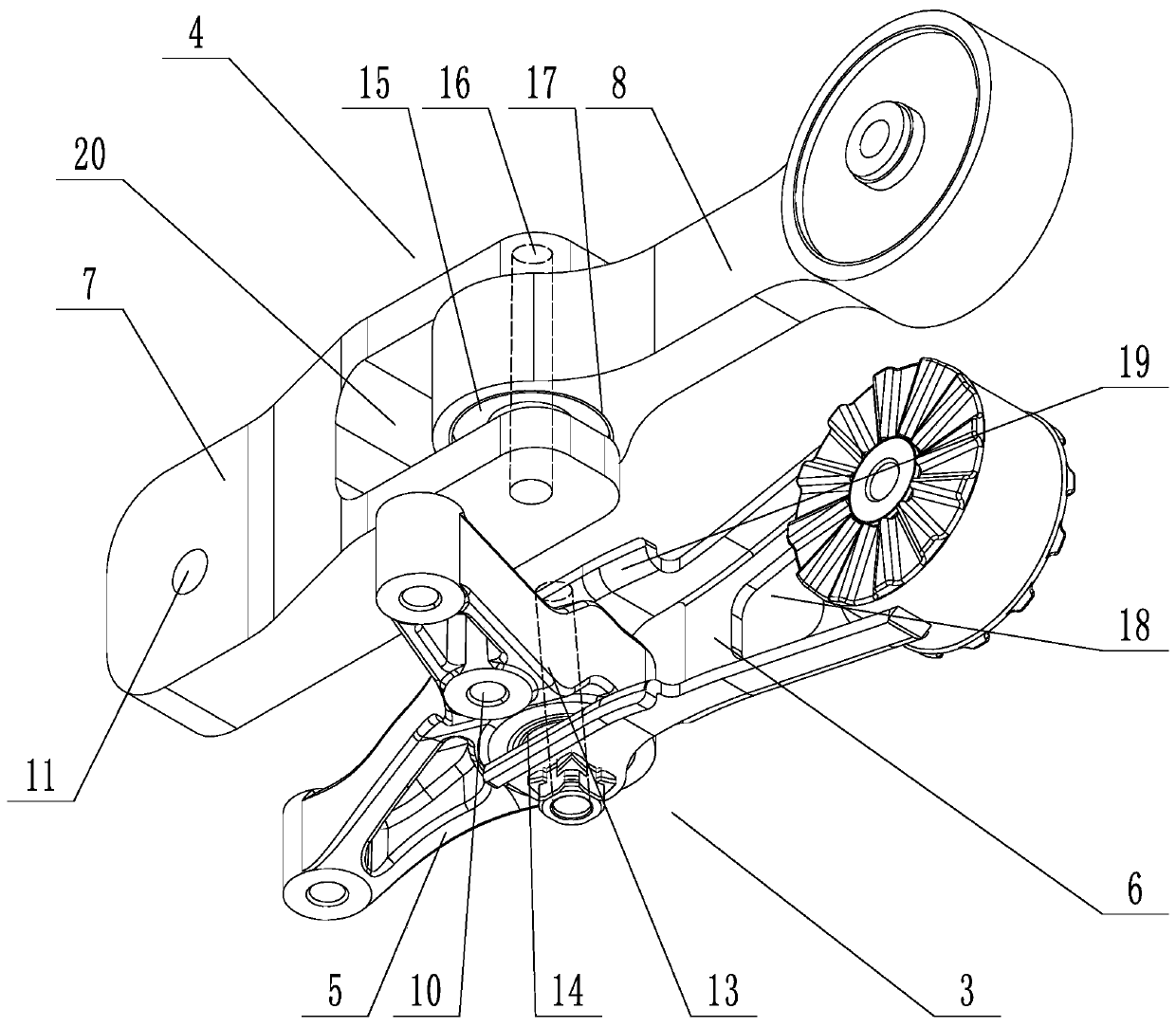
[0025] A rear suspension tie rod structure connected between the power assembly 1 and the front subframe 2, such as figure 1 As shown, it includes a power assembly 1, a front subframe 2 and a connection bracket connected between the power assembly 1 and the front subframe 2, the connection bracket includes a first connection bracket 3 and a second connection bracket 4, the first The connection bracket 3 includes a first rear suspension upper body 5 and a first rear suspension lower body 6, and the second connection bracket 4 includes a second rear suspension such as figure 2 As shown, the suspension upper body 7 and the second rear suspension lower body 8 , the first rear suspension upper body 5 and the second rear suspension upper body 7 are connected to the powertrain 1 .

[0026] The first rear suspension lower body 6 and the second rear suspension lower body 8 are fixedly connected to the front sub-frame 2, and the front sub-frame 2 is provided with buffer bosses 9, the f...

Embodiment 2

[0031] On the basis of embodiment 1, the present embodiment also includes:

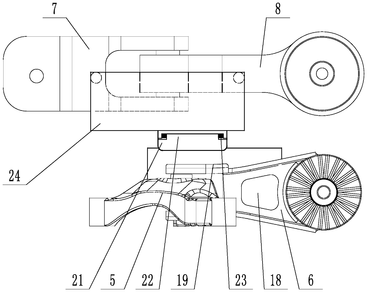
[0032] Such as image 3 and 4 As shown, the energy-absorbing bracket of the first connecting bracket 3 and the second connecting bracket 4, the torsion-resistant bracket includes two twisting blocks 21 that can rotate with each other, the twisting blocks 21 are in the shape of a round cake, and the center of a twisting block 21 is provided with a boss 22. The boss 22 is rotatably inserted in the center of another twist block 21. The two twist blocks 21 are arranged opposite to each other. A torsion spring 23 is hingedly connected between the two twist blocks 21. A vertical connection is provided on the twist block 21. Plate 24 has two connecting plates 24 in total. One connecting plate 24 extends upwards to be higher than the first connecting bracket 3, and the other connecting plate 24 extends downwards to be lower than the second connecting bracket 4. The connecting plate 24 is provided with a corres...


PUM


Abstract

The invention discloses a rear suspension pull rod structure for connecting a power assembly with a front sub frame. The rear suspension pull rod structure for connecting the power assembly with the front sub frame aims at solving the problem that an existing rear suspension pull rod cannot adapt to the increasingly high torque of an automobile acting assembly. The rear suspension pull rod structure for connecting the power assembly with the front sub frame comprises the power assembly, the front sub frame and a connecting bracket which is connected between the power assembly and the front subframe; the connecting bracket comprises a first connecting bracket and a second connecting bracket; the first connecting bracket comprises a first rear suspension upper body and a first rear suspension lower body; the second connecting bracket comprises a second rear suspension upper body and a second rear suspension lower body; the first rear suspension upper body and the second rear suspensionupper body are connected to the power assembly; the first rear suspension lower body and the second rear suspension lower body are fixedly connected to the front sub frame; the first rear suspension upper body is hinged and connected to the first rear suspension lower body; and the second rear suspension upper body is hinged and connected to the second rear suspension lower body. The displacementof the power assembly is avoided, the jumping of the power assembly is avoided, and therefore, noises and vibrations are reduced, and better taking feeling is brought.

Description

technical field [0001] This invention relates to automotive body components, and more specifically, it relates to a rear suspension tie-rod structure that connects the powertrain to the front subframe. Background technique [0002] The rear suspension tie rod of the car is an important component connecting the engine and the body. With the continuous improvement of automobile design and technology, some of the previous suitable structures will be outdated, and new structures need to be replaced to meet new requirements. The powertrain of the current car is getting more and more advanced, and the torque provided by the unit power is getting bigger and bigger. On the one hand, it provides the car with better acceleration, climbing ability and suspension. up the challenge. The prevalence of electric vehicles also brings new challenges to the car body. Compared with gasoline vehicles, the greater torque of electric vehicles provides better acceleration and "push back feeling"....

Claims


Application Information

Patent Timeline
IPC IPC(8): B60K5/12B62D21/11
CPCB60K5/1208B62D21/11
Inventor 李建华
Owner ZHEJIANG LEAPMOTOR TECH CO LTD
Why Eureka
Try Eureka